Peak voltage detector and related method of generating an envelope voltage

a detector and envelope voltage technology, applied in the direction of electrical measurements, measurement devices, instruments, etc., can solve the problems of insufficient detection of peaks, low detection efficiency, and relatively slow amplifiers

Active Publication Date: 2016-04-14
STMICROELECTRONICS SRL
View PDF0 Cites 22 Cited by
  • Summary
  • Abstract
  • Description
  • Claims
  • Application Information

AI Technical Summary

Benefits of technology

[0025]According to one embodiment, a detector of voltage peak values adapted to generate an envelope voltage of an oscillating voltage is provided. The detector has an architecture realizable in a

Problems solved by technology

The amplifier is relatively slow thus, before being capable of following and compensating the variation, output undershoots/overshoots may occur.
A fast detection of peaks may be insufficient when they increase but also when their value decreases.
Indeed, if the detection of the peak reduction of the mains voltage is very slow, the setting of the correct feedforward action will be delayed, with a consequent excessive overshoot of the output voltage of the pre-regulator because of great variati

Method used


Image

  • Peak voltage detector and related method of generating an envelope voltage
  • Peak voltage detector and related method of generating an envelope voltage
  • Peak voltage detector and related method of generating an envelope voltage

Examples


Embodiment Construction

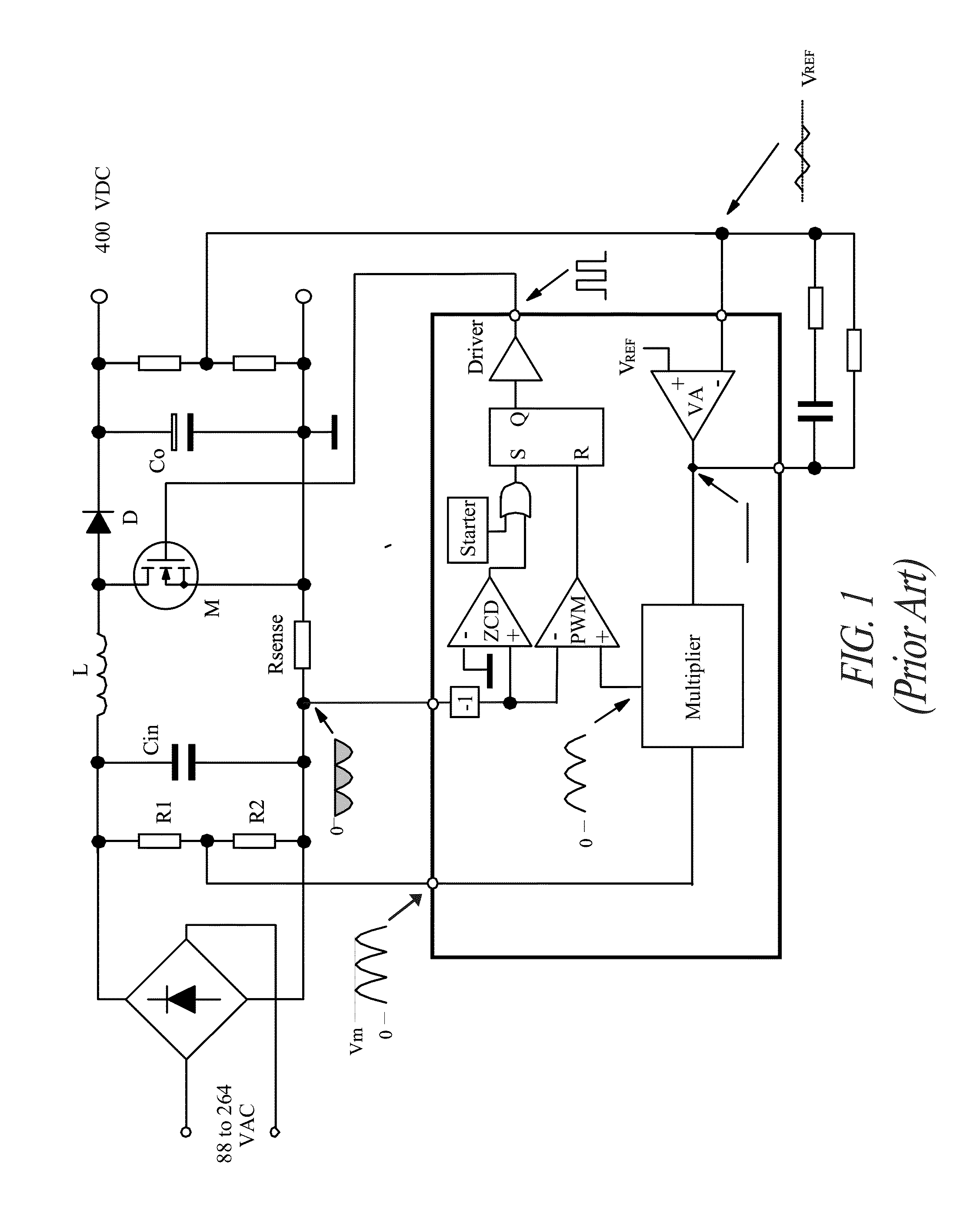
[0041]The circuit of FIG. 4 is burdened by the drawback of using two external discrete components RFF and CFF. Also, the activation time of the tracking mechanism (fast feedforward), tied to the constant RFFCFF and to a fixed threshold, will further depend from the value of the peak voltage itself. Therefore, the higher the input voltage, the longer the time that will elapse before the threshold is surpassed, and thus the slower the system when following eventual abrupt variations of the oscillating voltage VMULT.

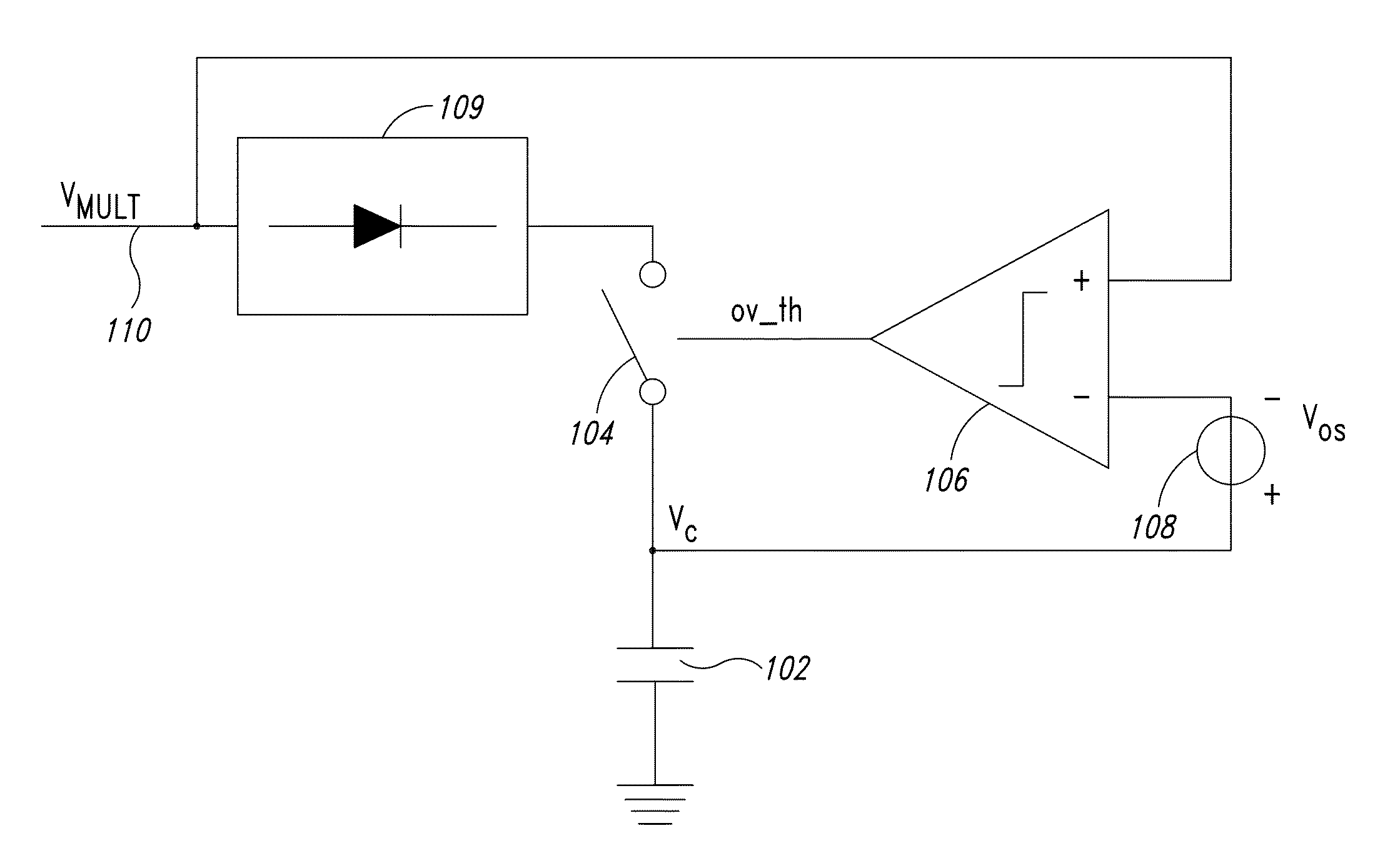
[0042]One embodiment of the present disclosure provides an architecture realizable in a completely integrated form that implements a related method for detecting the peak voltage of low frequency oscillating signals, without requiring external discrete components and capable of following abrupt variations of the oscillating input voltage and of keeping constant with a good approximation the envelope voltage between two consecutive peaks, if they have substantially the same ...


PUM


Abstract

A peak detector circuit receives an oscillating power supply signal. A capacitor is selectably coupled to the signal and charged to a value corresponding to a peak value of the signal. A switch is then opened to isolate the capacitor. When the signal rises to within a selected threshold, relative to the stored value, a comparator produces a command signal to close the switch, again coupling the capacitor to the signal. The peak detector can also include a tracking circuit that controls the capacitor to track the oscillating signal while the switch is closed, a timer circuit that closes the switch and activates the tracking circuit if more than a selected time passes without production of a command signal, a circuit that controls the polarity of a leakage current of the capacitor, a further auxiliary capacitor and a further auxiliary switch with a further control logic.

Description

BACKGROUND[0001]1. Technical Field[0002]This disclosure relates to detectors of voltage peaks of oscillating signals and more particularly to a novel architecture, realizable in a completely integrated form, adapted to generate an envelope voltage corresponding to the instantaneous peak value of an input oscillating voltage and to a related method.[0003]2. Description of the Related Art[0004]Forced switching power supplies and, more particularly, systems for active power factor correction (PFC), store information about peak values of an input voltage, that typically is the voltage of the mains, thus at a low frequency.[0005]In general, PFC pre-regulators are switching converters controlled such to obtain a regulated DC output voltage from an input AC voltage. Using particular switching techniques, PFC regulators are capable of absorbing a sinusoidal current in phase with the voltage of the mains, thus obtaining in this way a power factor close to 1 and a reduced total harmonic disto...

Claims


Application Information

Patent Timeline
IPC IPC(8): G01R19/04
CPCG01R19/04
Inventor GRAVATI, MIRKOTRIPODI, DOMENICO
Owner STMICROELECTRONICS SRL
Why Eureka
Try Eureka