
Hybrid direct-current circuit breaker

Active Publication Date: 2016-04-14
GENERAL ELECTRIC CO
View PDF1 Cites 4 Cited by
  • Summary
  • Abstract
  • Description
  • Claims
  • Application Information

AI Technical Summary

Benefits of technology

This patent describes a circuit breaker system that can protect a power line circuit in the event of an overload. The system includes two branches: one with a solid-state snubber and one with a superconductor and cryogenic contactor. When the current in the circuit is below a certain level, the system operates through the second branch. When the current is higher, the system activates the solid-state snubber to redirect the current to the first branch, and then the cryogenic contactor takes over to redirect the current to the second branch when the fault is cleared. This system helps to protect the power line circuit from damage caused by overload.

Problems solved by technology

However, these power systems may be damaged by short circuits and / or fault current in the load devices.
However, these electromagnetic circuit breakers are large in size.
Also, the electromagnetic circuit breakers have response times which are undesirably high for some applications, such as aircraft engines.
However, the on-resistance of the semiconductors reduces efficiency due to high conduction and / or electrical losses.

Method used


Image

  • Hybrid direct-current circuit breaker
  • Hybrid direct-current circuit breaker
  • Hybrid direct-current circuit breaker

Examples


Embodiment Construction

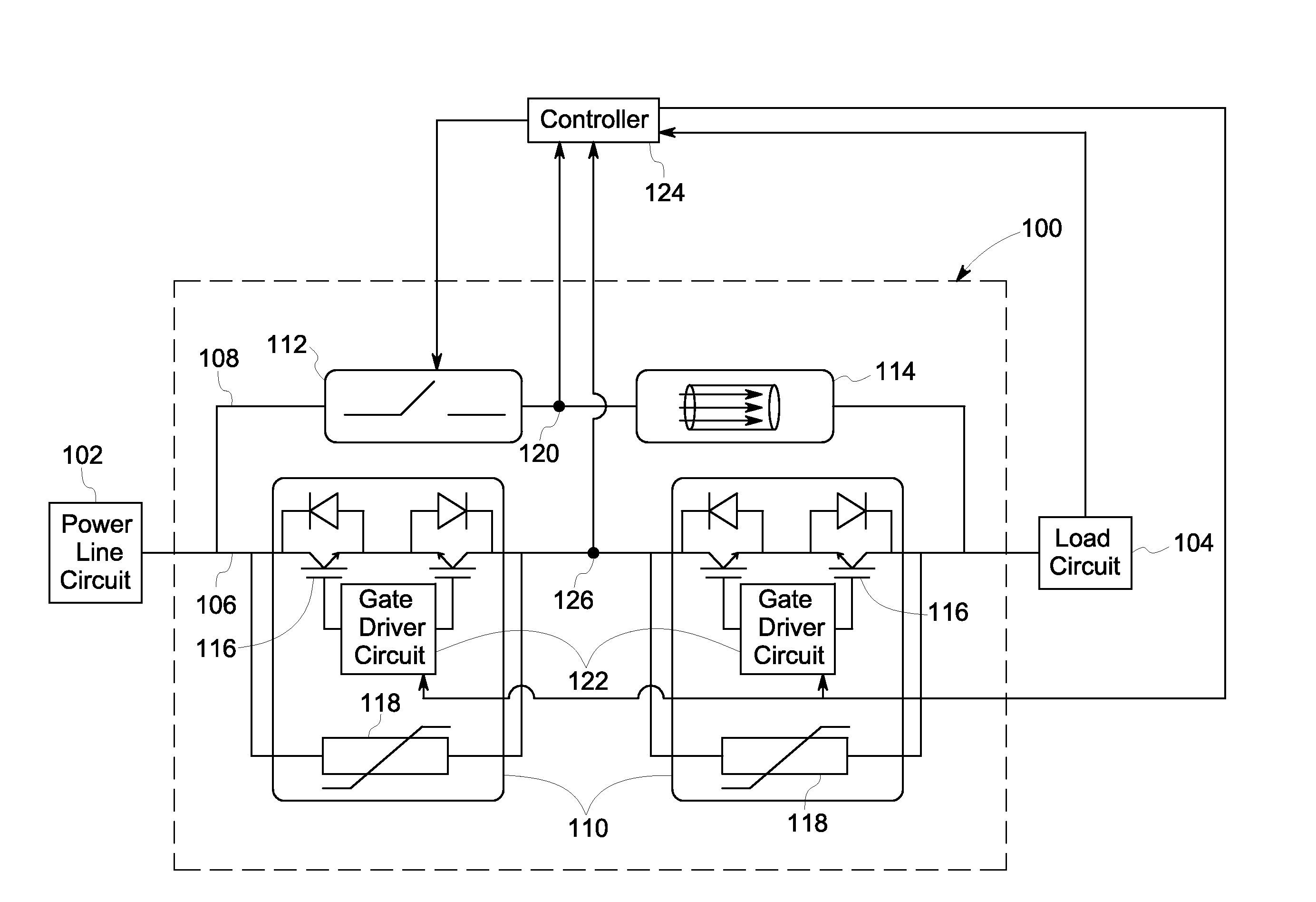
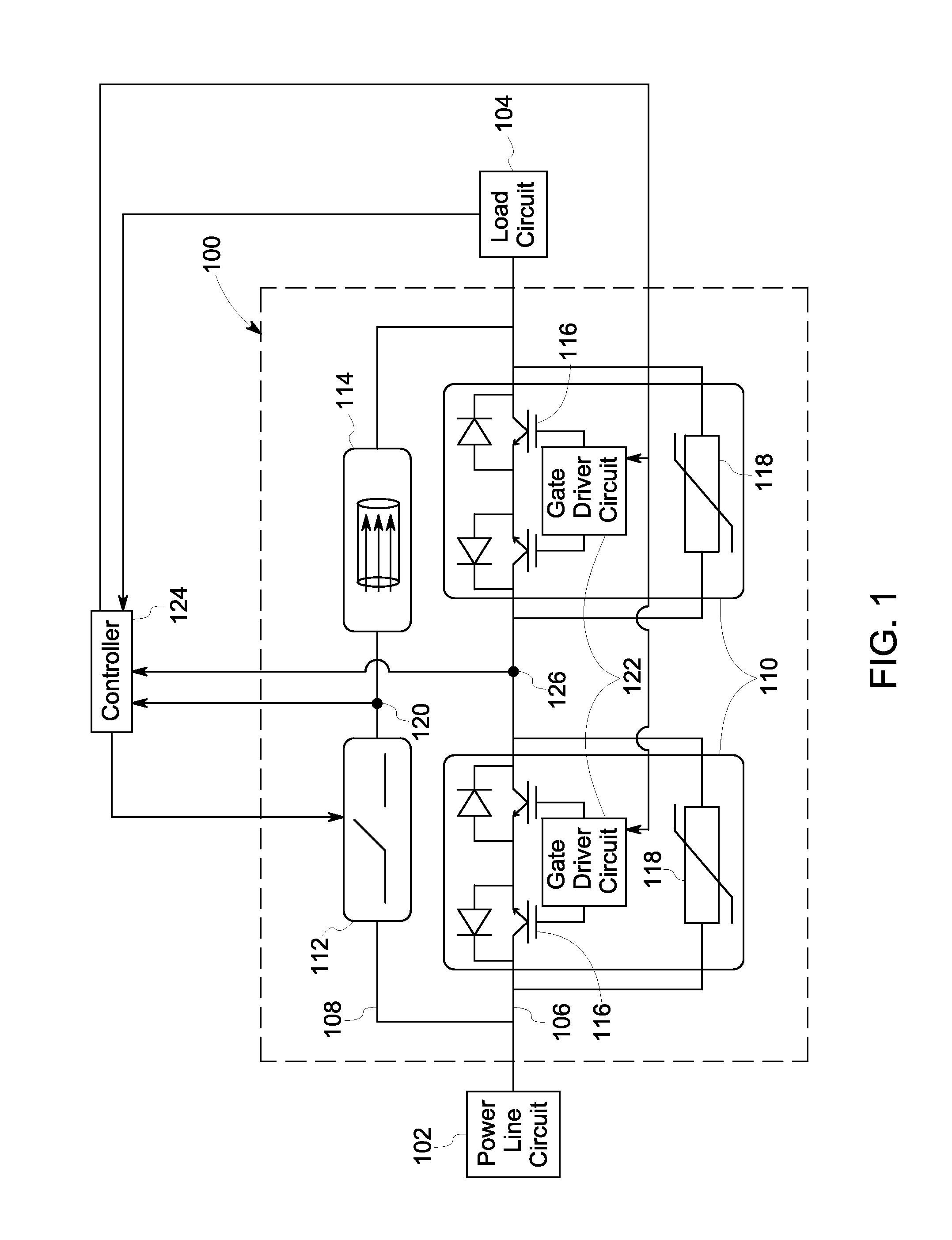
[0012]As will be described in detail hereinafter, various embodiments of an exemplary circuit breaker for isolating a power line circuit from the load circuit are presented. By employing the methods and the various embodiments of the circuit breaker described hereinafter, response time may be improved without sacrificing efficiency as the circuit breaker provides very low impedance to the flow of electrical current under normal operating conditions and keeping a reduced footprint.

[0013]Referring to FIG. 1, a diagrammatical representation of a circuit breaker 100, in accordance with one embodiment of the present disclosure, is depicted. The circuit breaker 100 is electrically coupled between a power line circuit 102 and a load circuit 104. The circuit breaker 100 is typically used to control flow of electrical current from the power line circuit 102 to the load circuit 104. The power line circuit 102 may be referred to as a power source that generates and / or distributes electrical po...


PUM


Abstract

A circuit breaking system includes a first branch including at least one solid-state snubber; a second branch coupled in parallel to the first branch and including a superconductor and a cryogenic contactor coupled in series; and a controller operatively coupled to the at least one solid-state snubber and the cryogenic contactor and programmed to, when a fault occurs in the load circuit, activate the at least one solid-state snubber for migrating flow of the electrical current from the second branch to the first branch, and, when the fault is cleared in the load circuit, activate the cryogenic contactor for migrating the flow of the electrical current from the first branch to the second branch.

Description

STATEMENT REGARDING FEDERALLY SPONSORED RESEARCH & DEVELOPMENT[0001]The invention described herein was made in the performance of work under NASA Contract No. NNC10BA06B and is subject to the provisions of Section 305 of the National Aeronautics and Space Act of 1958 (42 U.S. C. 2457).BACKGROUND[0002]The disclosure relates generally to a power protection system and more specifically to a direct-current (DC) circuit breaker in the power protection system.[0003]Power systems are widely used for generating and distributing power to one or more load devices. However, these power systems may be damaged by short circuits and / or fault current in the load devices. To protect these power systems, circuit breakers are used for instantaneously sensing the fault current and isolating the power systems from the load devices.[0004]In some conventional power systems, electromagnetic circuit breakers are used in conjunction with suitable means for sensing the fault current. However, these electroma...

Claims


Application Information

Patent Timeline
IPC IPC(8): H02H9/02
CPCH02H9/023H01H9/542H01H2009/543H03K17/92H01H9/541
Inventor WANG, RUXIPREMERLANI, WILLIAM JAMESCAIAFA, ANTONIOPAN, YAN
Owner GENERAL ELECTRIC CO
Features
  • Generate Ideas
  • Intellectual Property
  • Life Sciences
  • Materials
  • Tech Scout
  • Unparalleled Data Quality
  • Higher Quality Content
  • 60% Fewer Hallucinations
Learn More