Frequency synthesis device and method

a frequency synthesis and frequency technology, applied in the field of frequency, can solve the problems of high spectral impurity (phase noise), unstable output signal provided by the oscillator b>12/b> alone, and first frequency dividers

Active Publication Date: 2016-04-14
COMMISSARIAT A LENERGIE ATOMIQUE ET AUX ENERGIES ALTERNATIVES
View PDF1 Cites 0 Cited by
  • Summary
  • Abstract
  • Description
  • Claims
  • Application Information

AI Technical Summary

Benefits of technology

[0022]One purpose of the present invention is to provide a new type of frequency synthesis device not having the previously set forth drawbacks of the frequency synthesis de

Problems solved by technology

The output signal provided by the oscillator 12 alone is unstable in the RF's frequency bands and micro-wave, drifts over time and has a high spectral impurity (phase noise).
The major drawback of this type of frequency synthesis device 10 is to use a long string of frequency dividers 14 in view of the high value of N when the difference between fquartz and f1 is great.
The first frequency dividers (those on the oscillator 12 side) operating at high frequencies have a high static electricity consumption.
But, this feedback can lead the PLL to instabilities (non-locking of the frequency f1) because this loop operates at a high frequency.
When the multiplication rank N is high (which is the case for a frequency synthesis device being part of an RF communication system), it is necessary to use a high number of frequency multiplier circuits to make the string 32, resulting in high consumption and occupied circuit area.
Furthermore, there is no programmable frequency multiplier circuit, which makes the rank N fixed

Method used


Image

  • Frequency synthesis device and method
  • Frequency synthesis device and method
  • Frequency synthesis device and method

Examples


first embodiment

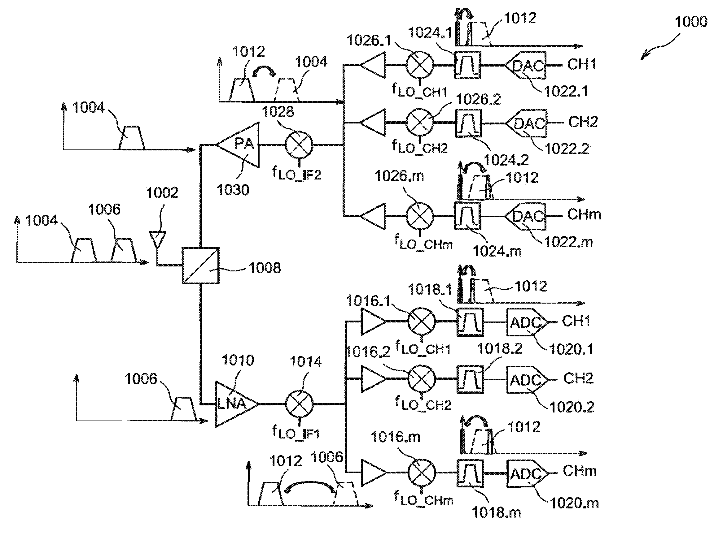
[0105]FIG. 6 is now referred to, which shows a frequency synthesis device 100 enabling frequency stable signals SLO_CH1 to SLO_CHm to be generated.

[0106]The device 100 includes an oscillator 102 for example of the VCO-type outputting a periodical signal S1 with a frequency f1, for example a sinusoidal one with an oscillation frequency f1. The frequency f1 can be assimilated to the value Δf used in the example of the previously described transceiver device 1000. The frequency f1 is controlled by a voltage applied to a control input 104 of the oscillator 102. In order to lock and stabilize the oscillation frequency f1 of the signal S1, the oscillator 102 is regulated by a phase-locked loop (PLL). This PLL includes one or more frequency dividers 106 able to divide the frequency of the signal S1 by an integer or fractional number A. At the output of the frequency divider(s) 106, a periodical signal with a frequency f1 / A is obtained, which is then compared with a very stable reference p...

second embodiment

[0142]FIG. 13 is referred to, which shows a frequency synthesis device 200 according to a

[0143]With respect to the previously described device 100, the oscillator 114 is no longer controlled by a periodically interrupted power source, but is continuously supplied, providing a sinusoidal signal with a frequency fOL. This signal is sent at the input of the switch 202 controlled by the periodical signal S1. The switch 202 is periodically (period T1) in a closed position for a duration equal to TH (for example equal to T1 / 2 in the case of a duty cycle of 0.5) and in an open position for a duration equal to T1-TH.

[0144]In this case, at the input of the circuits 118.1 to 118.m, a PROT type signal SG is obtained, that is of the oscillations-train type with a frequency fOL periodically repeated with a repetition period equal to T1. The oscillations of the oscillations trains of SG are generally not similar, in terms of phase, from one train to the other.

[0145]From the analytic point of view...

third embodiment

[0153]FIG. 17 shows a frequency synthesis device 300 according to a As the previously described device 100, the device 300 includes the elements 102, 106, 108, 110 and 112 for generating the periodical signal S1. Yet, the device 300 includes several PROT generators each including a VCO-type oscillator 114.1 to 114.m, each being voltage-controlled by a specific control signal Vctrl_114.1 to Vctrl_114.m, and controlled power supply means 116.1 to 116.m each associated with one of the oscillators 114.1 to 114.m and for example of a nature similar to the previously described means 116. Thus, m pulsed signals SG1 to SGm are generated, the control voltages Vctrl_114.1 to Vctrl_114.m being such that the centre frequencies of the pulsed signals SG1 to SGm are different from each other and correspond to the frequencies fLO_CH1 à fLO—CHm for being recovered via the frequency recovering circuits 118.1 to 118.m. FIG. 18 shows examples of spectra of the signals SG1 to SGm obtained.

[0154]This th...


PUM


Abstract

A frequency synthesis device, including: a first generator configured to generate a periodical signal with a frequency f1; a second generator, coupled to the first generator and generating from the signal with a frequency f1 a signal SG corresponding to a train of oscillations with a frequency substantially equal to N·f1, with a duration lower than T1=1/f1 and periodically repeated at the frequency f1; a third generator generating, from the signal SG, m periodical signals SLO_CH1 to SLO_CHm with frequency spectra each include a main line with a frequency fLO_CHi corresponding to an integer multiple of f1, with 1≦i≦m, the third generator operating as a band-pass filter applied to the signal SG and discarding from the frequency spectra of each of the periodical signals SLO_CH1 to SLO_CHm lines other than the main line with a frequency fLO_CHi.

Description

TECHNICAL FIELD[0001]The invention relates to the field of the transceiver devices, and in particular that of integrated wireless transceiver devices involving frequency stable signals for making one or more frequency translations in the transmitting and / or receiving part of these devices. The invention relates in particular to a frequency synthesis device and method enabling frequency stable signals to be provided from a stable signal with a lower frequency. The invention also relates to a device for transmitting and / or receiving signals, operating for example in the radiofrequency (RF) range, including such a frequency synthesis device for outputting stable periodical signals used upon transmitting-receiving signals.STATE OF PRIOR ART[0002]A frequency synthesis device enables a frequency stable signal for being used for example in an RF communication system to be provided. Thus, upon emitting signals, a signal containing the information to be sent can be modulated with the frequen...

Claims


Application Information

Patent Timeline
IPC IPC(8): H03L7/16
CPCH03L7/16H03L7/18H03L7/24H04B1/7174
Inventor SILIGARIS, ALEXANDREGONZALEZ JIMENEZ, JOSE-LUIS
Owner COMMISSARIAT A LENERGIE ATOMIQUE ET AUX ENERGIES ALTERNATIVES
Why Eureka
Try Eureka