AI technical title is built by Patsnap AI team. It summarizes the technical point description of the patent document.
a frequency synthesis and frequency technology, applied in the direction of transmission, pulse automatic control, electric devices, etc., can solve the problems of first frequency divider, high spectral impurity (phase noise), unstable output signal supplied by the oscillator b>12/b> alone,
Active Publication Date: 2015-12-08
COMMISSARIAT A LENERGIE ATOMIQUE ET AUX ENERGIES ALTERNATIVES
View PDF2 Cites 4 Cited by
Summary
Abstract
Description
Claims
Application Information
AI Technical Summary
This helps you quickly interpret patents by identifying the three key elements:
Problems solved by technology
Method used
Benefits of technology
Benefits of technology
The invention provides a device for frequency synthesis that overcomes the limitations of conventional frequency multipliers. It utilizes a high-ranking frequency multiplication without the need for a chain of frequency multipliers, reducing power consumption and size. The device is programmable, meaning it can be easily adjusted to different needs. It also has improved performance in terms of phase noise and frequency operating range. The device comprises a resonating device and a phase-locked loop, which ensures stable operation at low frequencies and reduces the risk of instability.
Problems solved by technology
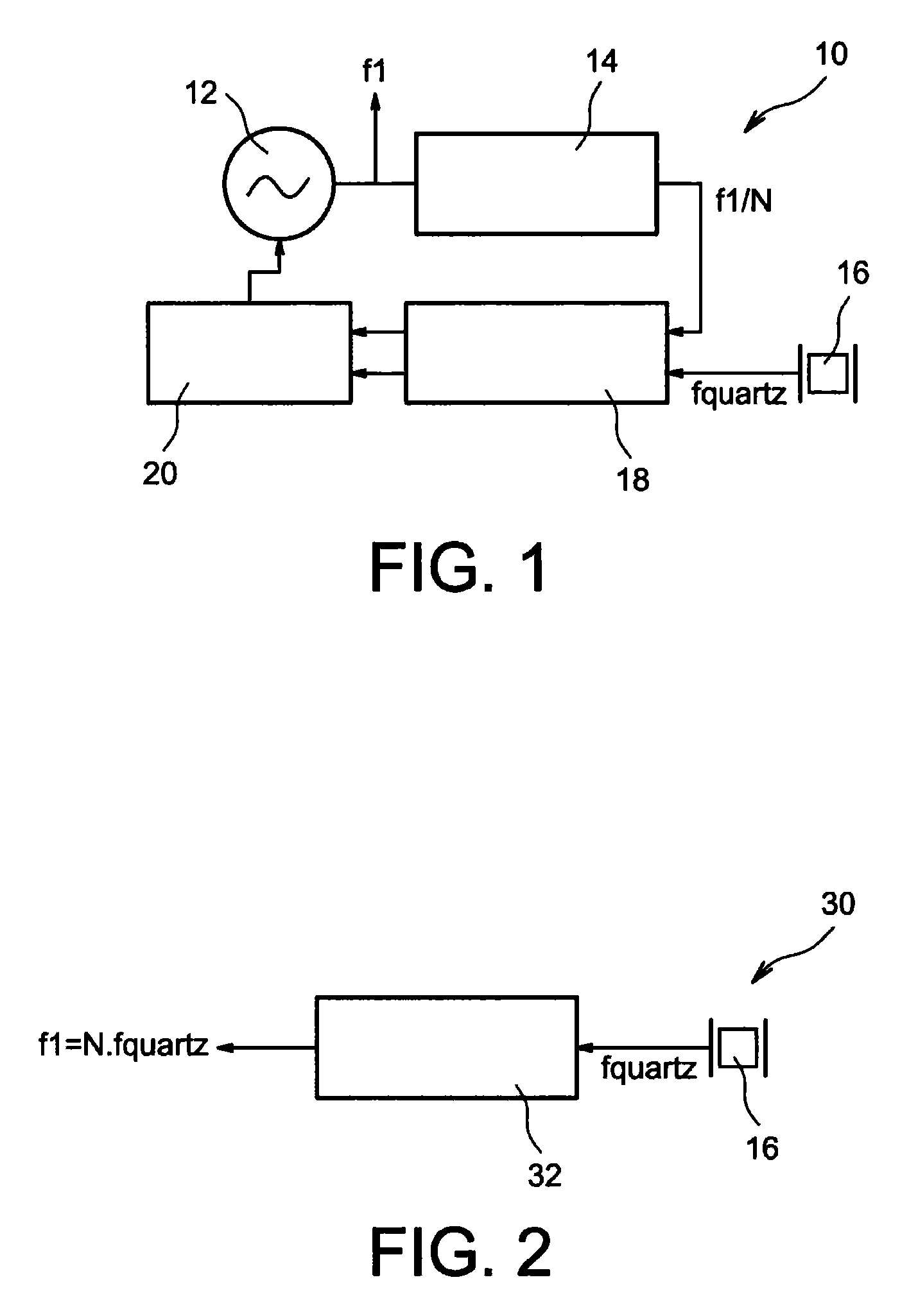
The output signal supplied by the oscillator 12 alone is unstable in the RF and microwave frequency bands, drifts over time and has a high spectral impurity (phase noise).
The first frequency dividers (those at the oscillator 12 end) operating at high frequencies have a high static electricity consumption.
When the multiplication rank N is high (which is the case for a frequency synthesis device including in an RF communicationsystem), it is necessary to use a large number of frequency multiplier circuits to produce the chain 32, giving rise to a high consumption and large occupied circuit area.
Furthermore, there is no programmable frequency multiplier circuit, rendering the rank N fixed and not enabling the device 30 to synthesise frequencies in a programmable manner.
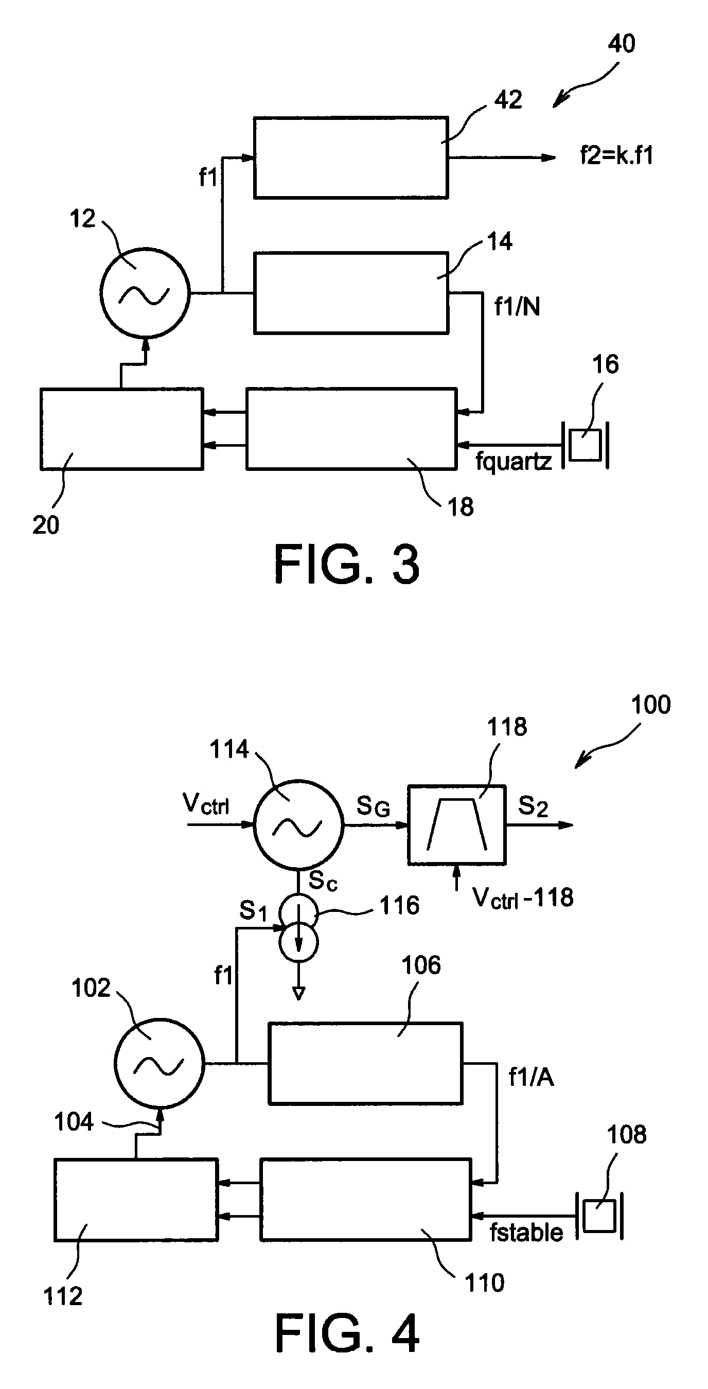
Although the frequency synthesis device 40 solves some of the drawbacks of the frequency synthesis devices 10 and 30, all these frequency synthesis devices involve the drawback of making use of complete chains of frequency dividers and / or multipliers of high ranks (N and K suitable for being in the region of several hundred or several thousand), due to the major differences between the carrier frequency values to be obtained at the output of the devices and the relatively low frequencies suitable for being supplied by stable resonators such as quartz resonators.
However, these complete frequency divider or multiplier circuit chains have a high electricity consumption and also occupy a large circuit area.
Method used
Image
Click on the blue label to locate the original text in one second.
Reading with bidirectional positioning of images and text.
Examples
first embodiment
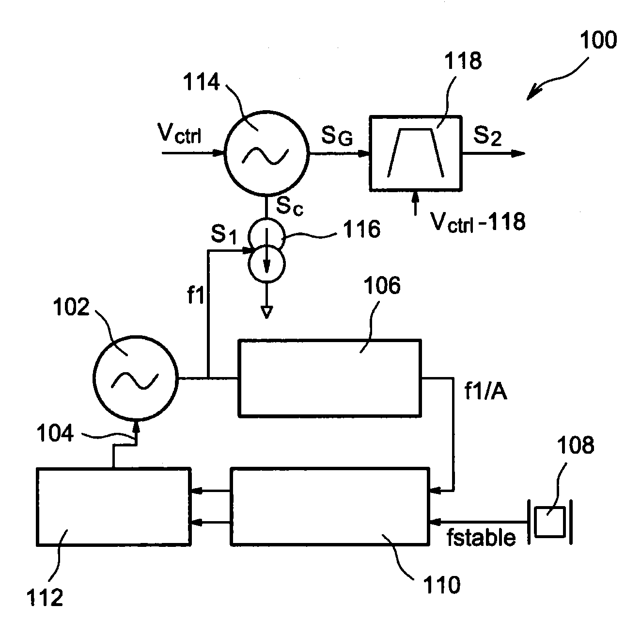
[0079]FIG. 4 schematically represents a frequency synthesis device, according to the present invention,
[0080]FIGS. 5A and 5B respectively represent the waveform and the spectrum of a signal SC generated in a frequency synthesis device, according to the present invention,
[0081]FIGS. 6A and 6B respectively represent the waveform and the spectrum of a signal SG generated in a frequency synthesis device, according to the present invention,
[0082]FIGS. 7A and 7B respectively represent the waveform and the spectrum of a signal S2 obtained at the output of a frequency synthesis device, according to the present invention,
[0083]FIG. 8 represents the selectivity of a frequency recovery circuit included in a frequency synthesis device, according to the present invention,
[0084]FIGS. 9A and 9B represent waveforms and spectra of the signals generated in a frequency synthesis device, according to the present invention,
[0085]FIG. 10 represents the spectrum of a signal SG generated in a frequency syn...
second embodiment
[0090]FIG. 15 schematically represents a frequency synthesis device, according to the present invention, according to a
[0091]Identical, similar or equivalent parts of the various figures described hereinafter bear the same reference numbers for easier transition from one figure to another.
[0092]The various parts represented in the figures are not necessarily based on a uniform scale, so as to render the figures more legible.
[0093]The various options (alternatives and embodiments) should be understood as not being mutually exclusive and suitable for being combined with each other.
PUM
Abstract
A frequency synthesis device including: a first generator configured to generate a periodic signal of frequency f1; a second and third generator, coupled with the first generator and configured to receive as an input the periodic signal of frequency f1 and to generate a signal SG corresponding to a train of oscillations of frequency substantially equal to N·f1, of a time less than T1=1 / f1 and repeated periodically at the frequency f1, where N is a whole number greater than 1; and a fourth generator configured to generate, from the signal SG, a periodic signal wherein a frequency spectrum includes a primary line of frequency f2=(N+i)·f1, where i is a whole number.
Description
FIELD OF THE INVENTION[0001]The invention relates to a frequency synthesis device and method for supplying a stable signal of a predetermined frequency from a signal of lower frequency. The invention also relates to a device for transmitting and / or receiving signals, operating for example in the radiofrequency (RF) range, comprising such a frequency synthesis device for outputting a stable periodic signal.STATE OF THE RELATED ART[0002]A frequency synthesis device is suitable for supplying a frequency-stable signal intended to be used for example in an RF communicationsystem. In this way, during a signal transmission, a signal containing the information to be sent can be modulated with the frequency-stable signal acting as the carrier signal for conveying the information.[0003]The frequency synthesis performed defines in this case the value of the transmission carrier frequency. During signal reception, frequency synthesis makes it possible to supply this frequency-stable signal to ...
Claims
Application Information
Patent Timeline
Application Date:The date an application was filed.
Publication Date:The date a patent or application was officially published.
First Publication Date:The earliest publication date of a patent with the same application number.
Issue Date:Publication date of the patent grant document.
PCT Entry Date:The Entry date of PCT National Phase.
Estimated Expiry Date:The statutory expiry date of a patent right according to the Patent Law, and it is the longest term of protection that the patent right can achieve without the termination of the patent right due to other reasons(Term extension factor has been taken into account ).
Invalid Date:Actual expiry date is based on effective date or publication date of legal transaction data of invalid patent.

