Overheat protector and protection methodology for electrodynamic loudspeakers

a loudspeaker and overheat protection technology, applied in the direction of transducer protection circuits, transducer circuits, electrical transducers, etc., can solve the problem of imposing excessive power into the voice coil of the loudspeaker, and achieve the effect of reducing possible audible artefacts

Active Publication Date: 2016-04-14
ANALOG DEVICES INT UNLTD
View PDF4 Cites 14 Cited by
  • Summary
  • Abstract
  • Description
  • Claims
  • Application Information

AI Technical Summary

Benefits of technology

[0027]According to one embodiment of the present methodology, level transitions from the first fixed level to the second fixed level, or vice versa, are gradual. These gradual transitions reduce possible audible artefacts which may be generated by an abrupt turn on or turn off of the low-frequency probe signal. According to this embodiment a level transition of the low-frequency probe signal from the first fixed level to the second fixed level, or vice versa, comprises an intermediate fading period exhibiting a gradual increase or decrease of level in accordance with a predetermined rate of level change. This feature is described in further detail below in connection with the appended drawings such as waveform graphs 701 and 703 of FIG. 7.

Problems solved by technology

The latter may be able force excessive levels of power into the voice coil of the loudspeaker and drive the temperature of the voice coil above a maximum temperature limit.

Method used


Image

  • Overheat protector and protection methodology for electrodynamic loudspeakers
  • Overheat protector and protection methodology for electrodynamic loudspeakers
  • Overheat protector and protection methodology for electrodynamic loudspeakers

Examples


Embodiment Construction

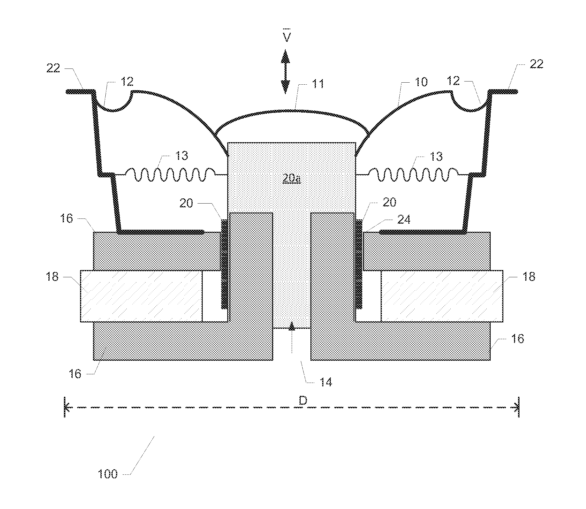
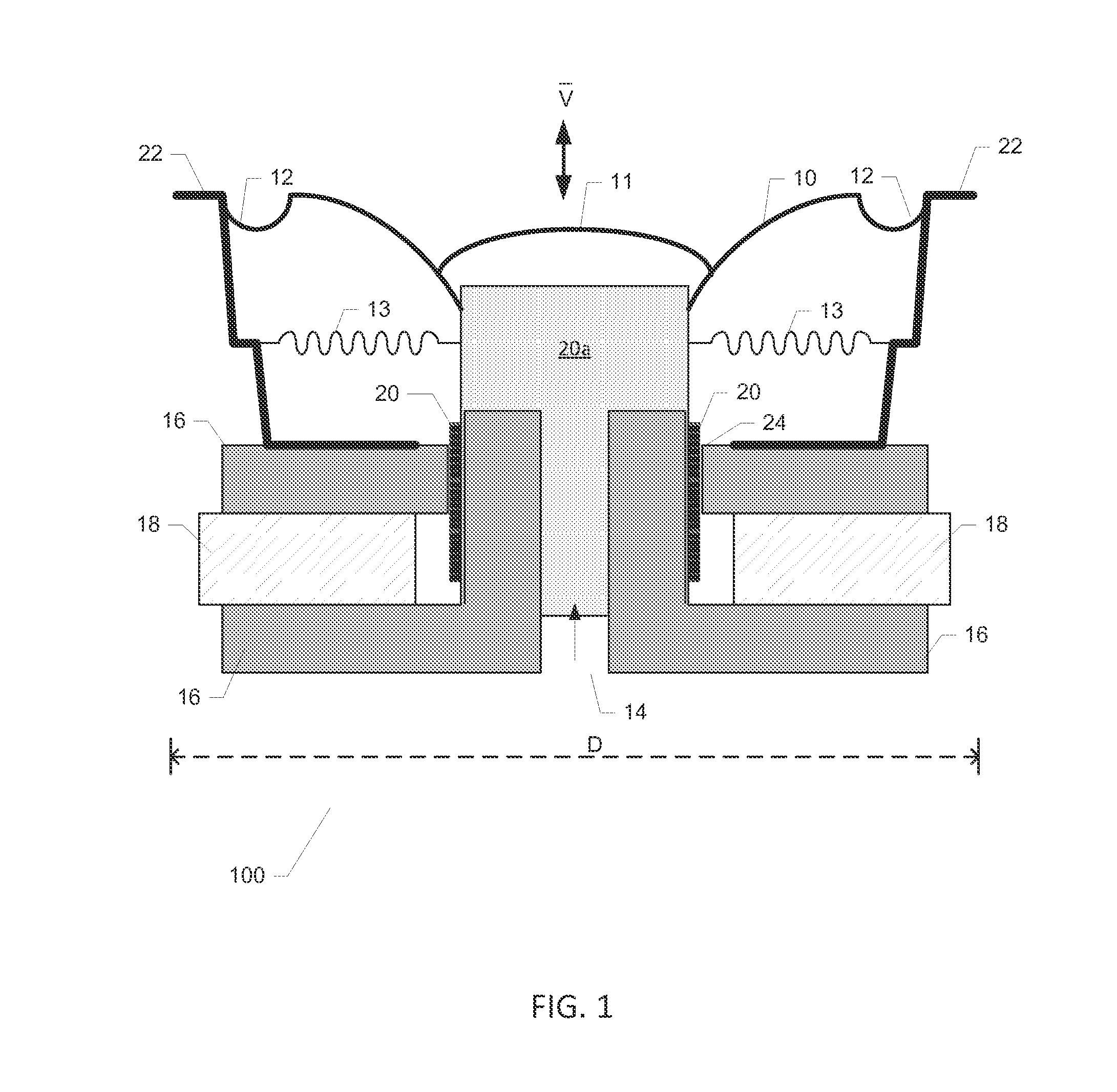
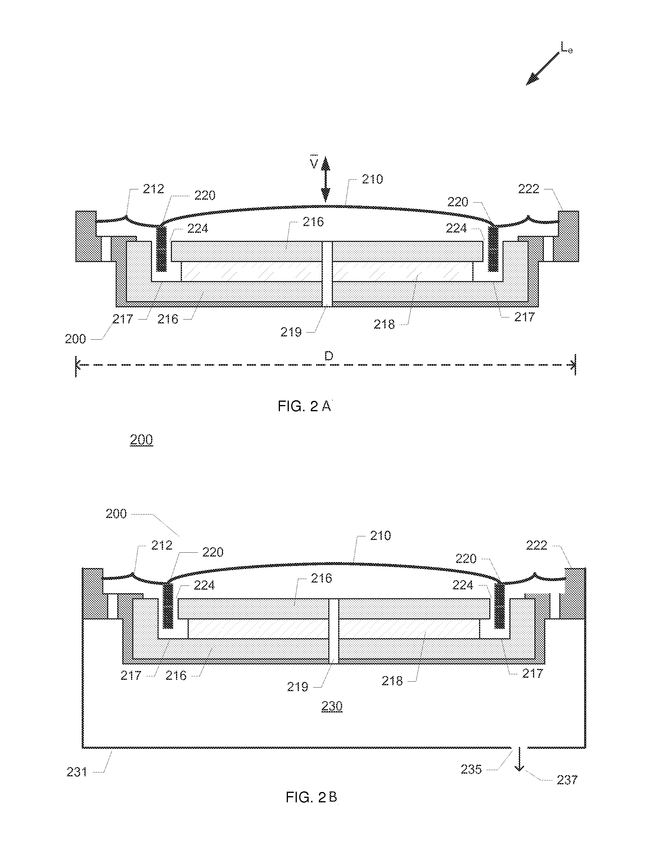
[0053]FIG. 1 is a schematic illustration of an exemplary electrodynamic loudspeaker 100 for use in various types of stationary audio applications such as Hi-Fi, automotive and home cinema. The skilled person will appreciate that electrodynamic loudspeakers exist in numerous shapes and sizes dependent on the intended type of application. The electrodynamic loudspeaker 100 used in the below described methodologies and devices for loudspeaker excursion detection and control has a diaphragm diameter, D, of approximately 6.5 inches, but the skilled person will appreciate that the present invention is applicable to virtually all types of electrodynamic loudspeakers, in particular to the miniature electrodynamic loudspeaker for sound reproduction in portable terminals such as mobile phones, smartphones and other portable music playing equipment illustrated on FIGS. 2A) and 2B).

[0054]The electrodynamic loudspeaker 100 comprises a diaphragm 10 fastened to a voice coil former 20a. A voice cou...


PUM


Abstract

The present invention relates in one aspect to a voice coil temperature protector for electrodynamic loudspeakers. The voice coil temperature protector comprises an audio signal input for receipt of an audio signal supplied by an audio signal source and a probe signal source for generation of a low-frequency probe signal. A signal combiner is configured to combine the audio signal with the low-frequency probe signal to provide a composite loudspeaker drive signal comprising an audio signal component and a probe signal component. The voice coil temperature protector comprises a current detector configured for detecting a level of a probe current component flowing through the voice coil in response to the composite loudspeaker drive signal and a current comparator which is configured to comparing the detected level of the probe current component with a predetermined probe current threshold. The predetermined probe current threshold corresponds to a predetermined voice coil temperature via a known temperature dependency of a voice coil resistance. The voice coil temperature protector further comprises a signal controller configured for attenuating a level of the audio signal in response to the probe current component falls below the predetermined probe current threshold.

Description

[0001]The present invention relates in one aspect to a voice coil temperature protector for electrodynamic loudspeakers. The voice coil temperature protector comprises an audio signal input for receipt of an audio signal supplied by an audio signal source and a probe signal source for generation of a low-frequency probe signal. A signal combiner is configured to combine the audio signal with the low-frequency probe signal to provide a composite loudspeaker drive signal comprising an audio signal component and a probe signal component. The voice coil temperature protector comprises a current detector configured for detecting a level of a probe current component flowing through the voice coil in response to the composite loudspeaker drive signal and a current comparator which is configured to comparing the detected level of the probe current component with a predetermined probe current threshold. The predetermined probe current threshold corresponds to a predetermined voice coil tempe...

Claims


Application Information

Patent Timeline
Patent Type & Authority Applications(United States)
IPC IPC(8): H04R3/00
CPCH04R3/007H04R9/06
Inventor BERTHELSEN, KIM SPETZLERSTRANGE, KASPER
Owner ANALOG DEVICES INT UNLTD
Why Eureka
Try Eureka