Supercharge Your Innovation With Domain-Expert AI Agents!

Antenna delay buffering in telecommunication receivers

a delay buffering and telecommunications receiver technology, applied in the field of telecommunication receivers, can solve the problems of different delay times, signal delay times corresponding with those distances will also not be the same, and require a large amount of memory

Active Publication Date: 2016-04-14
NXP USA INC
View PDF13 Cites 6 Cited by
  • Summary
  • Abstract
  • Description
  • Claims
  • Application Information

AI Technical Summary

Benefits of technology

The present invention is a telecommunication receiver, system, integrated circuit, computer program product, and method. The technical effects of the invention include improved signal quality, reduced interference, and improved overall communication performance. These features are achieved through a combination of hardware and software improvements, including advanced signal processing techniques, optimized antenna design, and efficient data transmission methods. The invention has been tested and validated in various telecommunication environments, and the technical effects have been shown to improve user experience and enhance overall efficiency of the telecommunication system.

Problems solved by technology

These sources may have different distances relative to the receiver, resulting in different delay times. That is, as the distances from the sources to the receiver are not the same, the signal delay times corresponding with those distances will also not be the same.
However, in many applications such an input buffer requires a large amount of memory, in particular when the number of antennas is large and / or when there is a large spread in the distances to the receiver and hence a large delay spread.
Especially in the case of one-chip receivers this memory requirement increases the cost of the receiver.
However, this known arrangement is designed to cancel interference and fails to address delay times.

Method used


Image

  • Antenna delay buffering in telecommunication receivers
  • Antenna delay buffering in telecommunication receivers
  • Antenna delay buffering in telecommunication receivers

Examples


Embodiment Construction

[0015]In the following, for sake of understanding, the circuitry is described in operation. However, it will be apparent that the respective elements are arranged to perform the functions being described as performed by them.

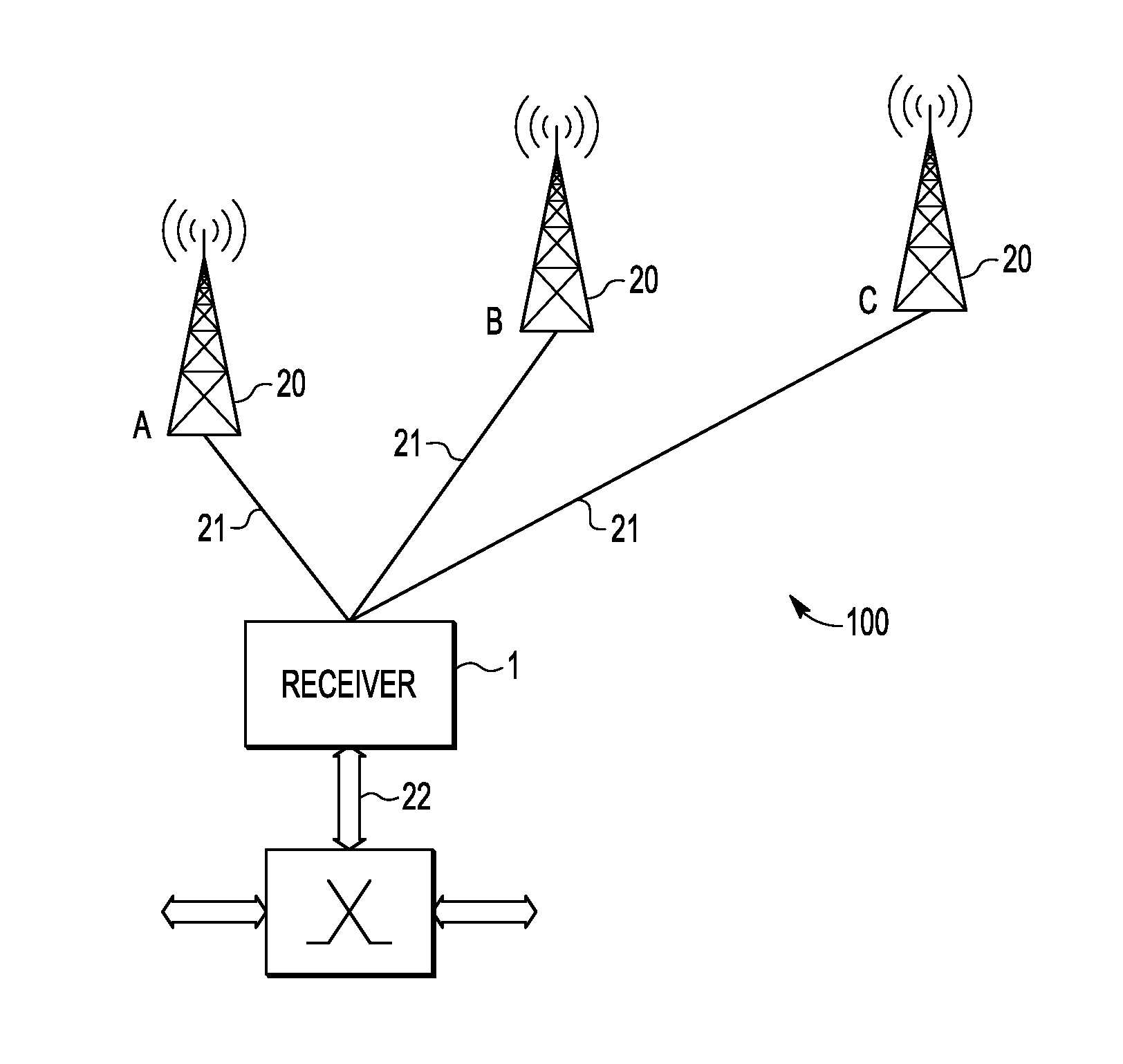
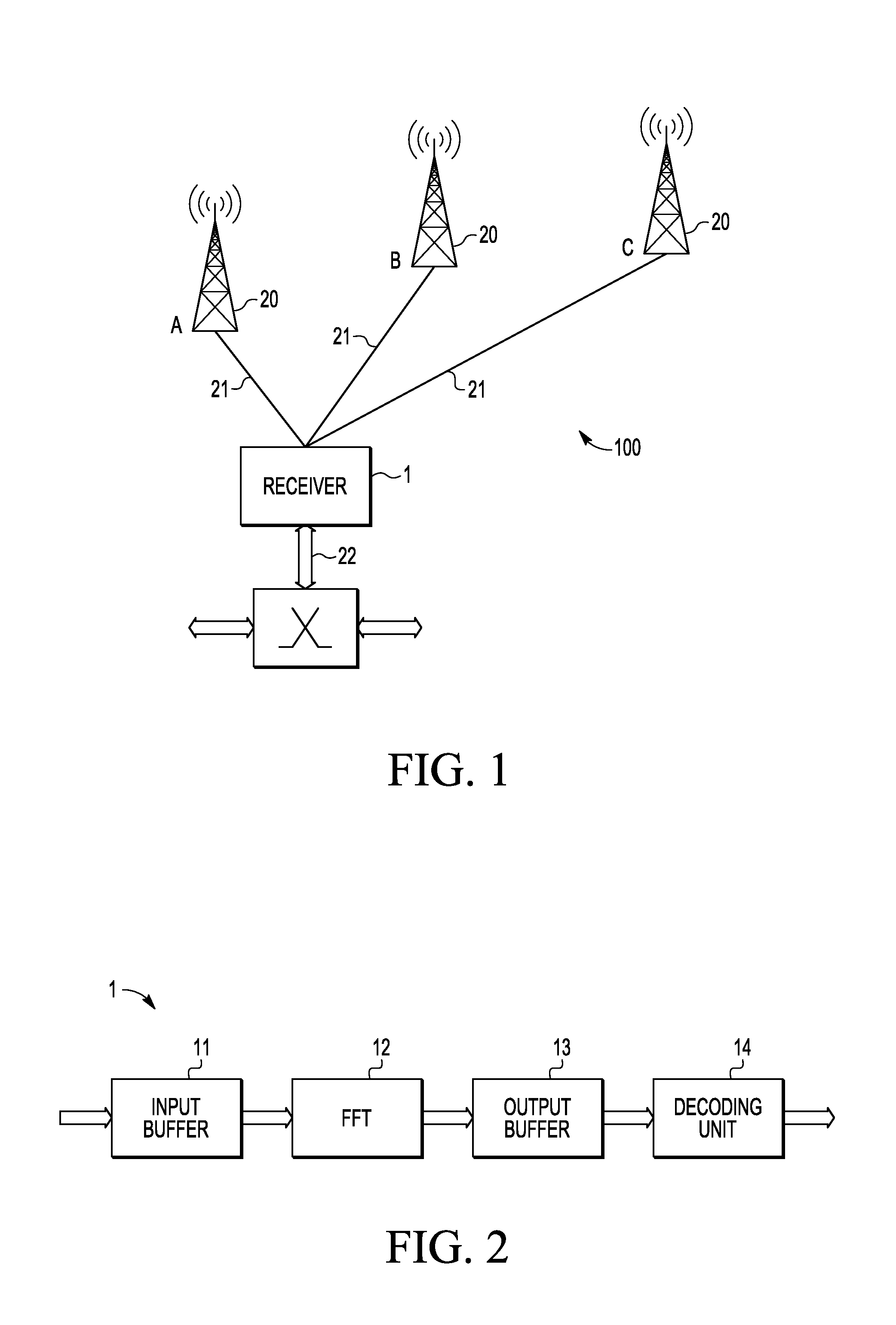
[0016]An example of a part of a telecommunication network is schematically illustrated in FIG. 1. The network 100 is shown to comprise a telecommunication receiver 1 and a plurality of antennas 20. In the example shown, the antennas 20 are coupled to the receiver 1 by fibre optic cables 21, although in other embodiments, wireless links or conventional copper cables can be used, for example copper cables using DSL (Digital Subscriber Line) techniques. For the sake of clarity, only three antennas 20 are shown, but in practice the number of antennas may be greater than three, but may also be equal to two. The receiver 1 and the antennas 20 may together constitute a cell (or macro cell) of a mobile telecommunication network, such as an LTE (Long Term Evolution) netw...


PUM


Abstract

A telecommunication receiver is arranged for receiving related data originating from multiple antennas, which data have different times of arrival due to, for example, different delays. The receiver comprises an input buffer for buffering data, a transform unit for Fourier transforming the data received from the input buffer into transformed data, and an output buffer for buffering the transformed data received from the transform unit. The input buffer is arranged for passing each set of data items to the transform unit when the relevant data item has been received in the input buffer, while the transform unit is arranged for removing redundant parts of the data. In addition, the output buffer is arranged for synchronizing the transformed data. Thus the buffering for delay compensation is carried out in the output buffer.

Description

FIELD OF THE INVENTION[0001]This invention relates to a telecommunication receiver, a telecommunication system, an integrated circuit, a computer program product, and a method for antenna delay buffering in telecommunication receivers.BACKGROUND OF THE INVENTION[0002]A telecommunication receiver may receive data signals from more than one source, for example from a plurality of antennas. These sources may have different distances relative to the receiver, resulting in different delay times. That is, as the distances from the sources to the receiver are not the same, the signal delay times corresponding with those distances will also not be the same. As a result of this delay spread, the instances of a signal that arrives at the antennas at approximately the same point in time will typically not arrive at the receiver at the same moment.[0003]In some telecommunication systems, multiple constituent signals are received by multiple antennas and forwarded to a central receiver, which pr...

Claims


Application Information

Patent Timeline
IPC IPC(8): H04W56/00H04J11/00
CPCH04W56/005H04J2011/0096H04W88/085H04J11/0063
Inventor MARTINEZ, VINCENT PIERRE
Owner NXP USA INC
Features
  • R&D
  • Intellectual Property
  • Life Sciences
  • Materials
  • Tech Scout
  • Unparalleled Data Quality
  • Higher Quality Content
  • 60% Fewer Hallucinations
Learn More