Coupling Device for a Laboratory Centrifuge Actuated by Centrifugal Force

Active Publication Date: 2016-04-21
SIGMA LABORZENTRIFUGEN
View PDF21 Cites 7 Cited by
  • Summary
  • Abstract
  • Description
  • Claims
  • Application Information

AI Technical Summary

Benefits of technology

[0014]A coupling device actuated by centrifugal force with a coupling lever according to prior art might in some cases be disadvantageous, because the pivotable support of the coupling lever necessitates additional bearing effort up to the use of a rolling bearing, which with an increase of the necessary m

Problems solved by technology

A coupling device actuated by centrifugal force with a coupling lever according to prior art might in some cases be disadvantageous, because the pivotable support of the coupling lever necessitates additional beari

Method used


Image

  • Coupling Device for a Laboratory Centrifuge Actuated by Centrifugal Force
  • Coupling Device for a Laboratory Centrifuge Actuated by Centrifugal Force
  • Coupling Device for a Laboratory Centrifuge Actuated by Centrifugal Force

Examples


Embodiment Construction

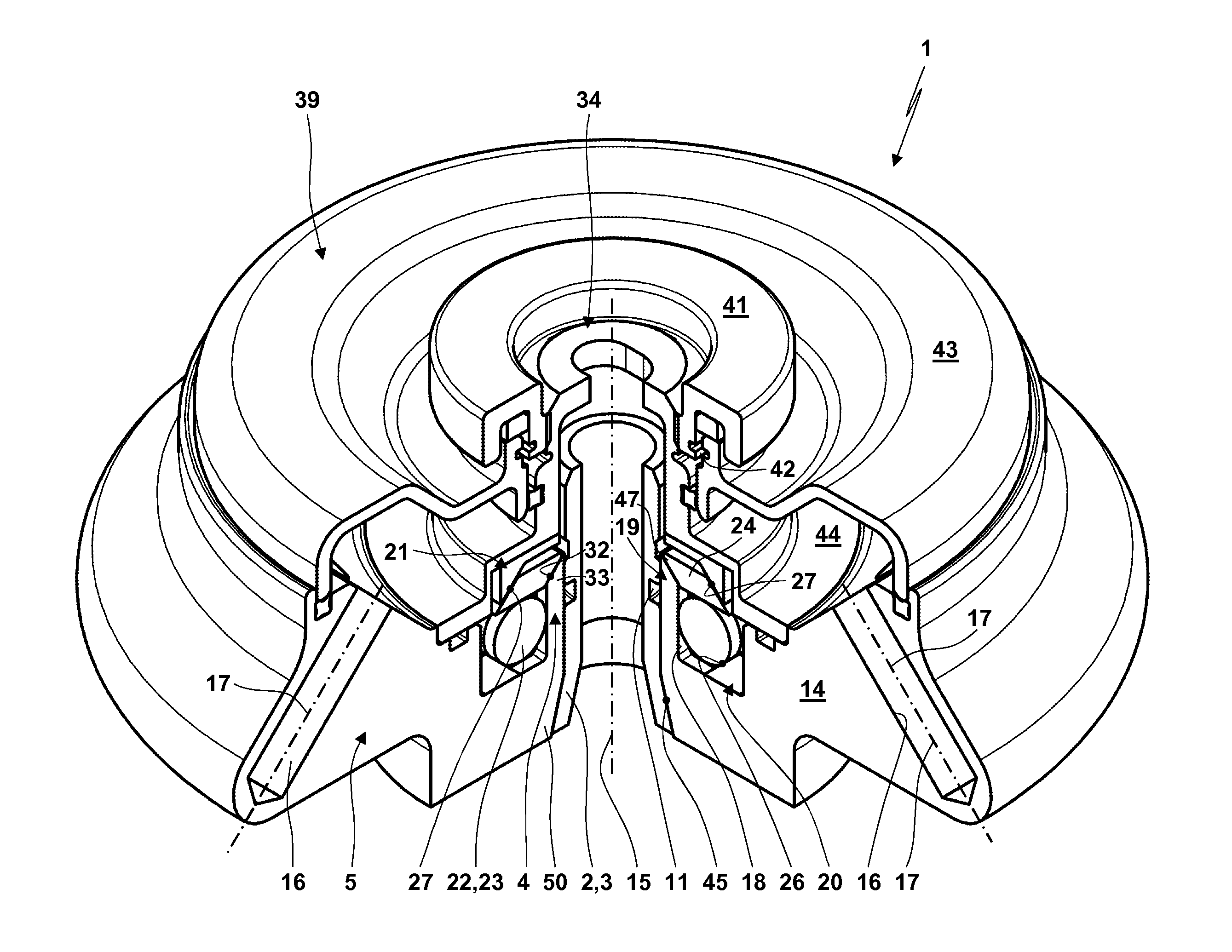
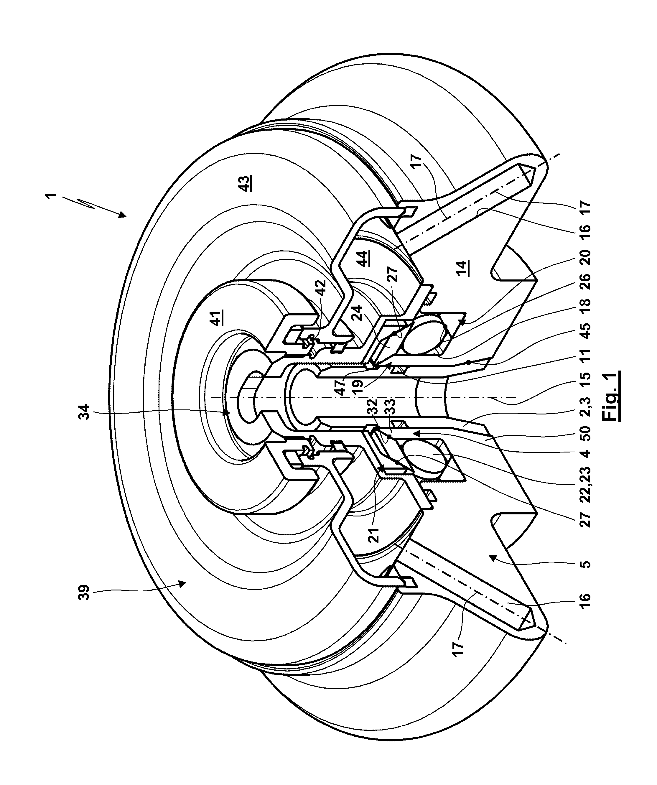
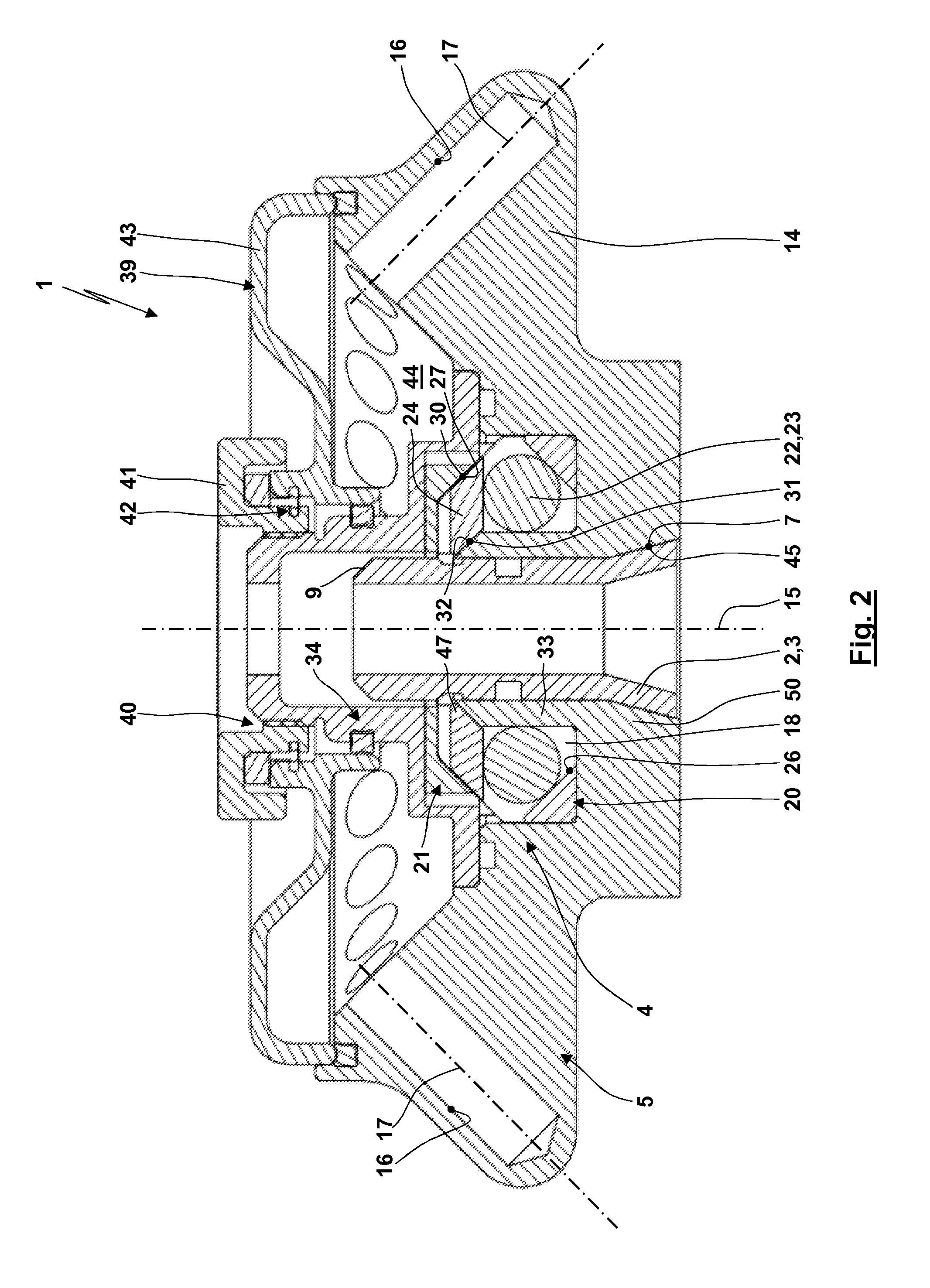
[0036]Referring now in greater detail to the drawings, FIGS. 1 to 5 illustrate a part of a laboratory centrifuge 1. The laboratory centrifuge 1 has a driving element 2 realized as a driving shaft 3 and an output element 50 coupled to the driving element 2 through a coupling device 4 realized by a rotor 5. For simplification, further parts of the laboratory centrifuge 1, especially a motor, control electronics and an interface with a display and input elements as well as a housing to be closed with a lid are not shown.

[0037]For the embodiment shown, the driving shaft 3 is realized as a hollow shaft (cp. FIG. 5). The driving shaft 3 has a partial lateral surface 6 in the shape of a truncated cone with which an opposite friction surface 7 is realized. In an upward direction, that is in the direction of the interior of the rotor 5, the partial lateral surface merges into a cylindrical partial lateral surface 8 of the driving shaft 3. On its front side the cylindrical partial lateral sur...


PUM


Abstract

The invention relates to a laboratory centrifuge (1) with a coupling device (4) actuated by a centrifugal force. According to the invention an eccentric mass (22), especially a roller (23), is guided through a guideway (26) and preferably another guideway (27, 32) in such a way that the centrifugal force (46) of the eccentric mass (22) is deflected in such a way that a coupling force is generated which presses a coupling element (24) radially inwards against the outer surface of a drive shaft (3).

Description

CROSS REFERENCE TO RELATED APPLICATIONS[0001]This application claims priority to co-pending European patent application No. EP 14 189 739.7 entitled “Zentrifugalkraftbetätigte Kupplungseinrichtung für eine Laborzentrifuge”, filed Oct. 21, 2014.FIELD OF THE INVENTION[0002]The invention relates to a coupling device for a laboratory centrifuge actuated by centrifugal force. Furthermore, the invention relates to a laboratory centrifuge with such a coupling device actuated by centrifugal force.BACKGROUND OF THE INVENTION[0003]Laboratory centrifuges have a rotor, which has receptacles distributed over its circumference. Into these receptacles vessels can be inserted in which substances to be treated by centrifuging are stored. To cause the rotor with the vessels with the substances accommodated in the receptacles to rotate with a rotation required for the centrifuging, an output element of the rotor is coupled with a driving element of the laboratory centrifuge, usually formed by a drivin...

Claims


Application Information

Patent Timeline
IPC IPC(8): B04B9/08F16D43/18
CPCB04B9/08B04B2009/085F16D43/18B04B2007/025F16D1/116F16D43/16
Inventor BITTNER, MATTHIAS
Owner SIGMA LABORZENTRIFUGEN
Why Eureka
Try Eureka