
Sheet holder

Active Publication Date: 2016-04-21
CARON JEAN +1
View PDF22 Cites 1 Cited by
  • Summary
  • Abstract
  • Description
  • Claims
  • Application Information

AI Technical Summary

Benefits of technology

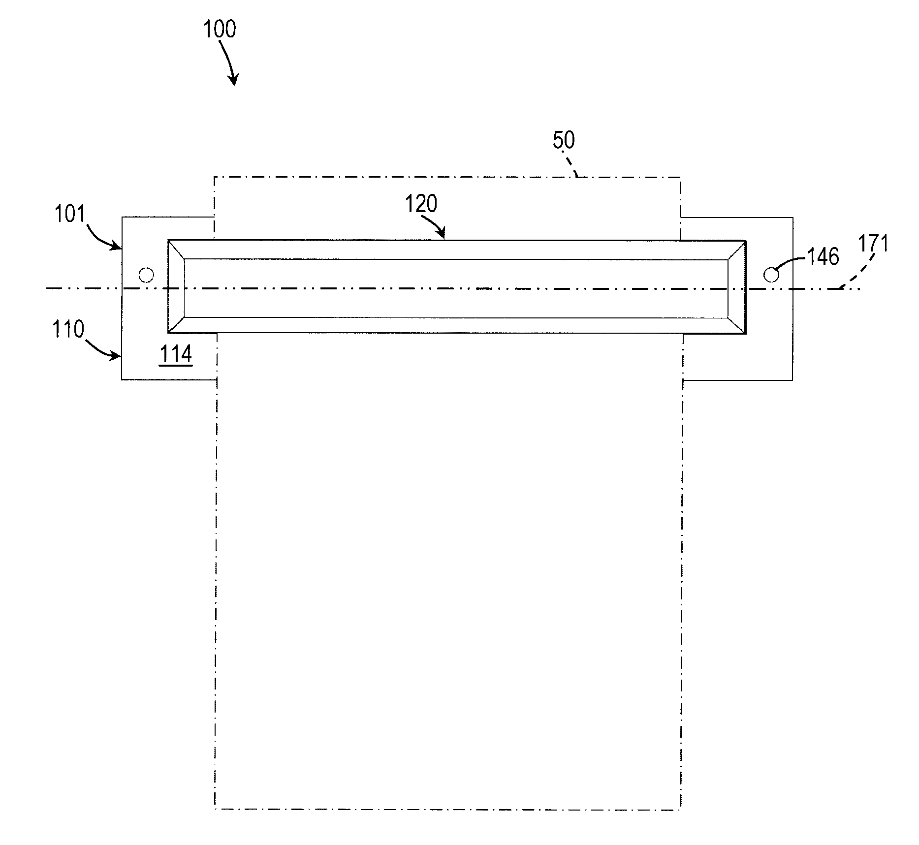
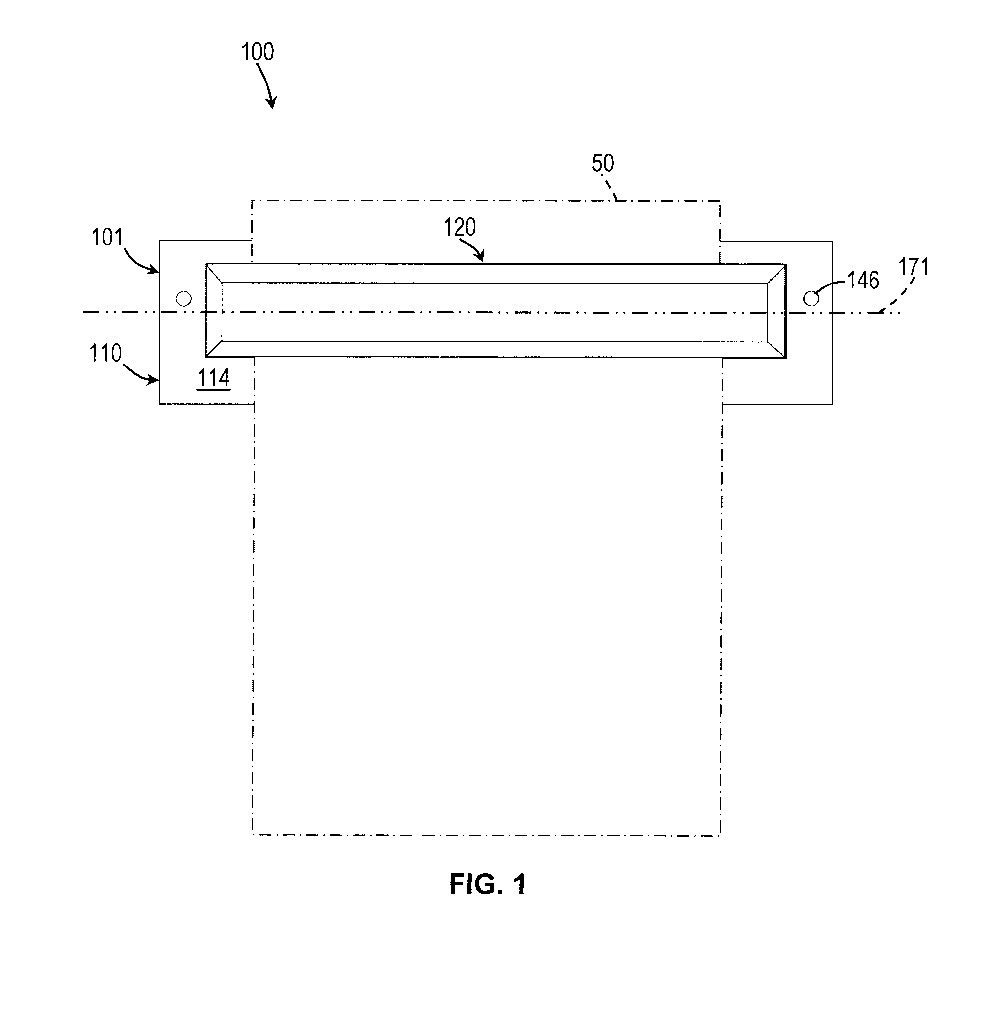
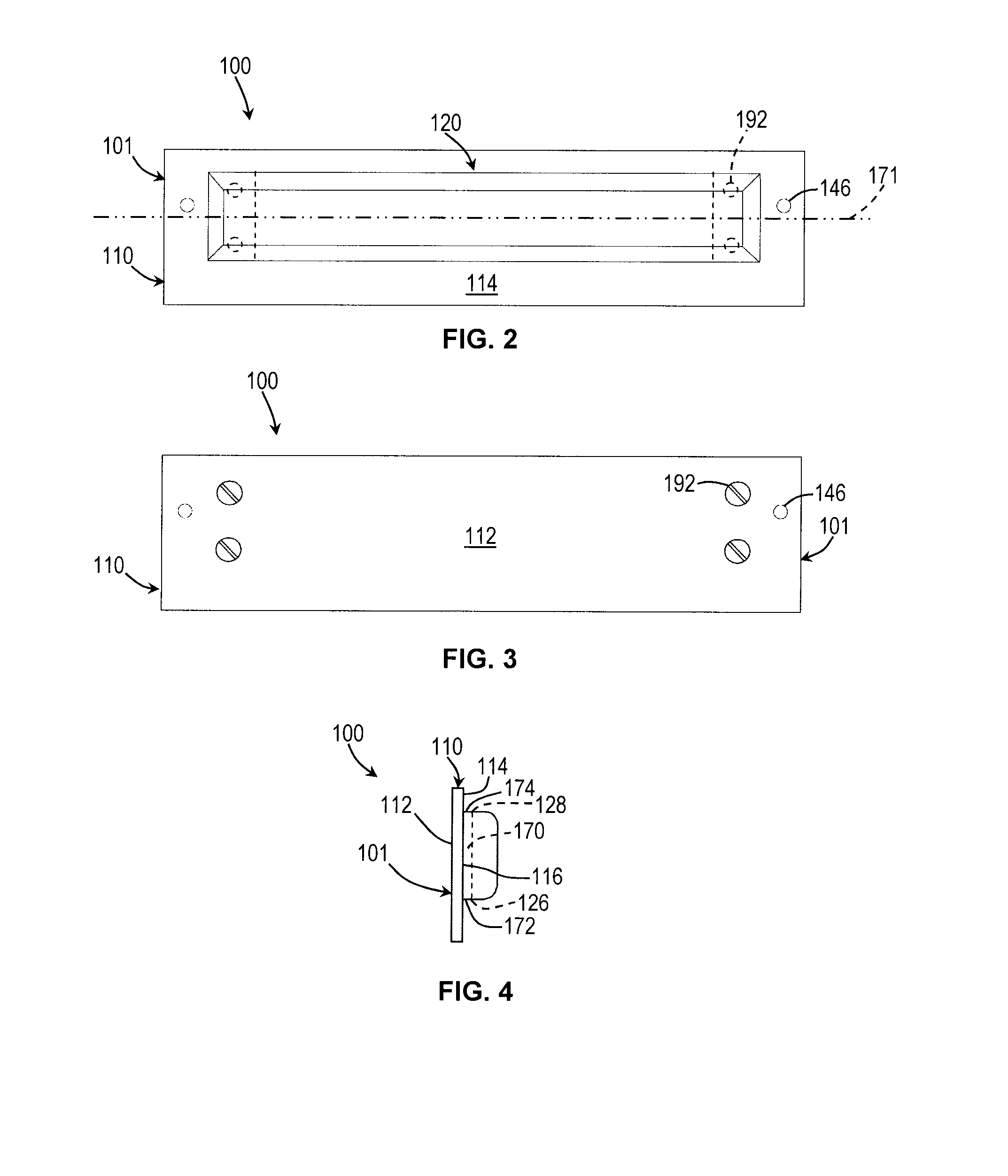
The invention is a sheet holder for a printing machine that prevents sheets from moving around when they are inserted through a slot. The holder has holding elements and guiding grooves that create a perpendicular force on the sheet to keep it in place. The guiding grooves have larger spaces at the bottom, which allows the holding elements to move more easily in the slot. This design prevents the sheet from tilting or marking when it is being held in place. The holder also has a parking element that prevents the control element from moving to its second position when it is in its first position. Overall, the sheet holder ensures that sheets can be held securely and easily removed from the printing machine.

Problems solved by technology

While these prior art sheet holders can generally fulfill the main objective of holding one or more sheets such as sheets of paper in a suspended attitude along a wall surface or the like, they also generally entail one or more of the following disadvantages in achieving this same objective.
For example, the sheet holders of the prior art integrating spring loaded paper gripping means generally require two hands to operate, which is inconvenient.
Furthermore, over time, the spring loaded elements generally impinge marks or dents in the surface of the sheets such as sheets of paper, which is generally not desirable either.
In the case of sheet holders of the prior art integrating gravity operated paper gripping means, these devices are typically more prone to holding the sheet at a slightly different angle than their original angle at which they were inserted through the input slot.
For example, the sheet holders integrating a series of individual roller elements, such as spherical rollers or cylindrical rollers, cannot ensure that these rollers all apply an equal gripping pressure against the sheets of paper, which results in an imbalance of load.
Consequently, sheets of paper sometime eventually end up being held at an angle relative to the horizontal, or fall off the sheet holder.
This problem is more present in sheet holders integrating free rolling cylindrical elements since their gripping pressure applied on the sheets are more evenly distributed along the length of the elements which, in turn, significantly reduces the gripping action on the sheets of paper.
Furthermore, in order to remove the sheets from sheet holders of the prior art integrating gravity operated paper gripping means, typically, the sheets must be forcibly pulled down against the engaging force of the roller elements, which often results in damaging marks on the surface of one or more sheets pulled therefrom.
Another disadvantage of the sheet holders of the prior art resides in that their gripping means are configured such that they are limited to hold sheets of material having surface characteristics closely corresponding to conventional thin sheets of paper used in offices.
Thus, these devices can hardly be used to hold sheets made of different materials having varied surface characteristics such as is often encountered in industrial applications.
For example, these sheet holders of the prior art can hardly be used for holding sheets of material made of felt, wet fiber-mat, shaggy carpets, semi-rigid textiles, tarpaulin sheets, sheets of soft or hard rubber or foam, corrugated rubber sheets, or the likes.

Method used


Image

  • Sheet holder
  • Sheet holder
  • Sheet holder

Examples


first embodiment

[0124]FIG. 23A illustrates yet another alternate embodiment of a sheet holder 1000, according to the present invention. Sheet holder 1000 is substantially similar to a sheet holder 100 described further above. Likewise sheet holder 100, sheet holder 1000 generally includes a second side wall 1110 attachable to a vertical support structure, a first side wall 1120 parallel and spaced apart from the second side wall 1110, and a substantially elongated slot 1170 extending between the first and second side wall 1120 and 1110.

embodiment 1000

[0125]In some alternate embodiments of a sheet holder (not shown in the drawings), the slot 1170 may only have a single opening (not visible in FIG. 23A) along a lower edge portion thereof (e.g., slot 1170 does not extends vertically all the way through the gap between first and second side walls 1120 and 1110), since the aperture along the upper surface of the first side wall 1120 may be optional. This optional aperture will be more apparent from the following description of the present embodiment 1000.

[0126]As illustrated in FIG. 24B and 24C, sheet holder 1000 also generally includes a plurality of dumbbell shaped holding elements 1102 freely rollably engaged in a corresponding number of spaced apart and compatibly shaped guiding grooves 1134 extending in the first side wall 1120 from the slot 1170.

[0127]Now referring more particularly to FIGS. 23B, 24A, 24B and 24C, the difference of the present embodiment of a sheet holder 1000 relative to sheet holder 100 substantially resides ...


PUM


Abstract

A sheet holder (100) for holding sheets (50) comprising a housing (101) defining first and second side walls (120 and 110) spaced apart from each other and defining a slot (170) therebetween. The first and second side walls (120 and 110) also define a bottom aperture (172) leading into the slot (170). A plurality of guiding grooves (134) are defined in the first side wall (120) facing the slot (170). The guiding grooves (134) define substantially opposed groove top and bottom ends (136 and 138) and extend further away from the second side wall (110) adjacent the groove top end (136) than adjacent the groove bottom end (138). Holding elements are each at least partially received in a respective one of the guiding grooves (134) and movable therealong. At least part of the holding elements (134) remains in the guiding grooves (134) at all positions therealong.

Description

FIELD OF THE INVENTION[0001]The present invention relates generally to sheet holders and, more particularly, to a sheet holder adapted for holding one, or a stack of more than one, sheets.BACKGROUND[0002]The prior art proposes numerous sheet holders that are useful for holding one sheet, or a relatively small stack of sheet-shape materials such as, for examples, sheets of paper, metal foils, plastic films, or the likes, in a freely suspended attitude along typically a vertical surface such as a wall surface, a door surface, or the likes.[0003]Sheet holders of the prior art are generally represented by a substantially elongated assembly that is typically attached horizontally at a suitable height along a vertical wall surface or a similar vertical support structure. The assembly further generally defines at least one elongated slot along a longitudinal lower front edge thereof for inserting therein the upper edge of one, or a stack of more than one, sheet. The most common sheet holde...

Claims


Application Information

Patent Timeline
IPC IPC(8): B42F15/06F16M11/04F16M13/02
CPCB42F15/066F16M11/041F16M13/02B42F1/00B42F15/06
Inventor CARON, JEANDES LAURIERS, ALEXANDRE
Owner CARON JEAN
Learn More