Vaporizing/discharging container, and flying insect pest repellent device using the vaporizing/discharging container

a technology of vaporizing/discharging containers and flying insect pests, which is applied in the direction of liquid handling, packaging, transportation and packaging, etc., can solve the problems of difficult vertical removal of the closure and the inability to easily remove the closure from the container body, and achieve good safety and convenience

Active Publication Date: 2016-04-21
ZHONGSHAN FUJI CHEM +2
View PDF6 Cites 0 Cited by
  • Summary
  • Abstract
  • Description
  • Claims
  • Application Information

AI Technical Summary

Benefits of technology

[0008]In this regard, in the air freshener container of Patent Document 1, the opening portion of the container in an unused condition is sealed using a sealing member so that the contained substance is not released into the outside, and therefore, safety may be ensured when the air freshener container is not used. However, just before use, the sealing member is peeled off to open the opening portion of the container body, and the cap is engaged with the protruding portion of a side surface of the container body. Therefore, a child can easily remove the cap from the container body with his or her strength. Note that Patent Document 1 does not teach or suggest that the air freshener container has a lock mechanism or the like for preventing removal of the cap.
[0030]According to the flying insect pest repellent device thus configured, an aqueous gel bead type flying insect pest repellent having the flying insect pest repellent effect is contained as a volatile substance in the vaporizing / discharging container of the present invention. Therefore, a flying insect pest repellent device having good safety and convenience can be provided.

Problems solved by technology

Here, screw containers are widely used as a container for a volatile substance, because once the closure is attached to the container body, it is difficult to remove the closure in the vertical direction, and it is easy to attach the closure to the container body.
When the closure is screwed all the way onto the container body, the protrusion on the closure fits into a space between the two protrusions on the container body, so that the closure is not easily removed from the container body.

Method used


Image

  • Vaporizing/discharging container, and flying insect pest repellent device using the vaporizing/discharging container
  • Vaporizing/discharging container, and flying insect pest repellent device using the vaporizing/discharging container
  • Vaporizing/discharging container, and flying insect pest repellent device using the vaporizing/discharging container

Examples


first embodiment

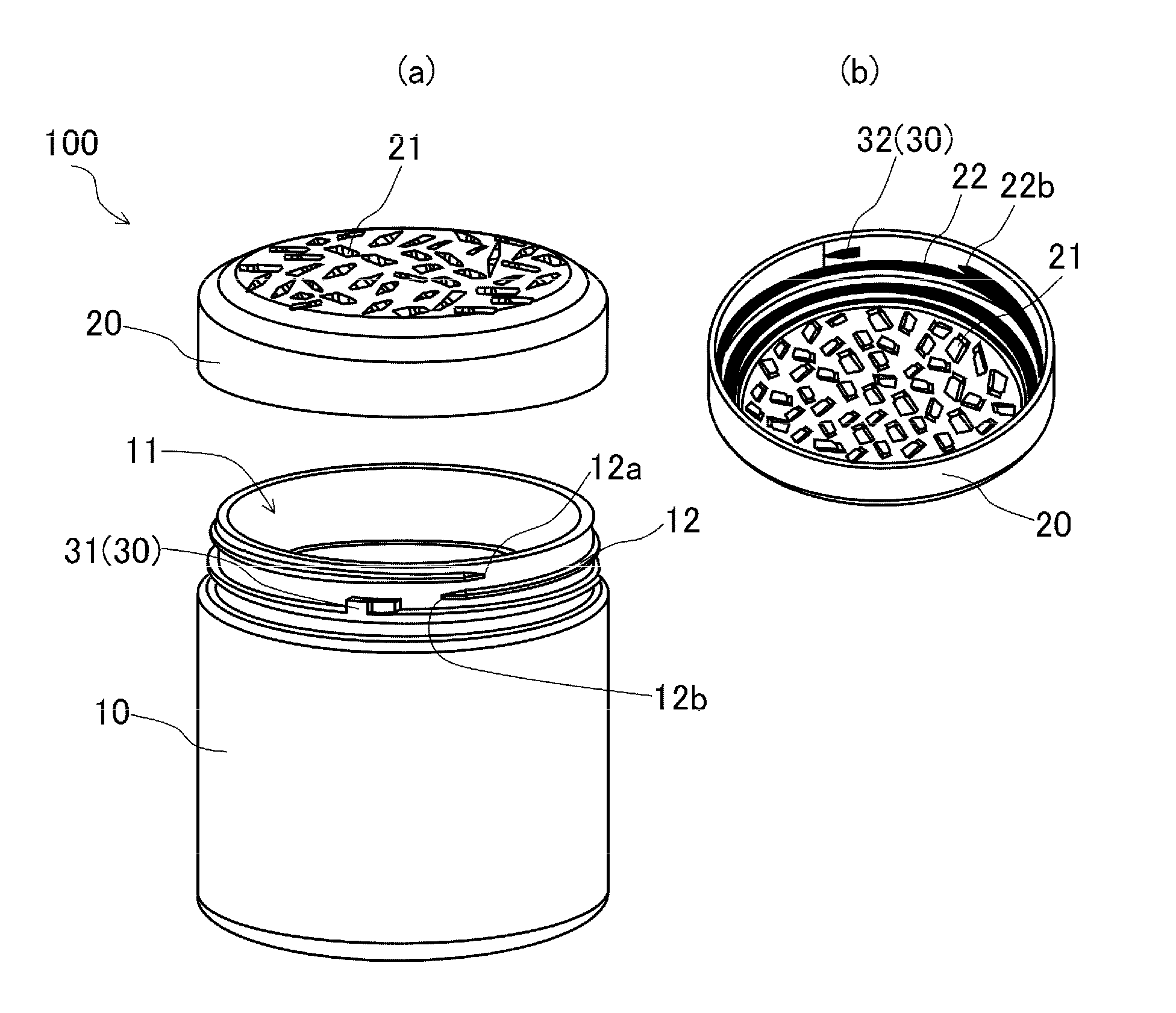
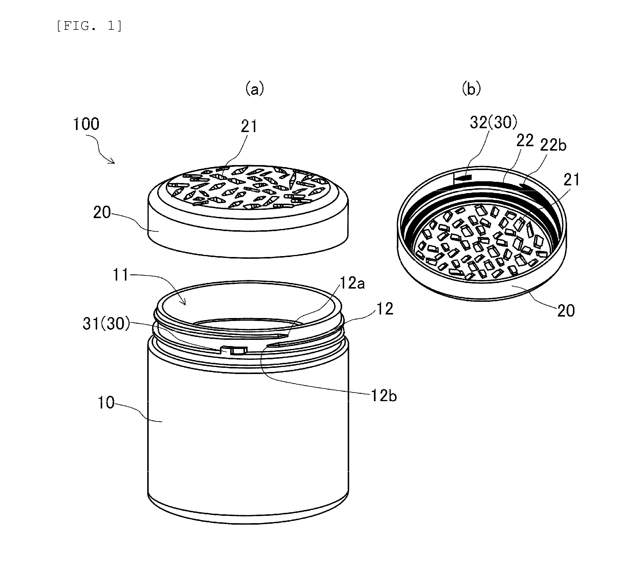
[0039]FIG. 1 is a perspective view of a vaporizing / discharging container 100 according to a first embodiment of the present invention. FIG. 1(a) shows the vaporizing / discharging container 100 with a closure member 20 being removed from a main body 10. FIG. 1(b) shows the closure member 20 as viewed from below. The vaporizing / discharging container 100 is a container that is used to vaporize and discharge a volatile substance described below into the outside. The vaporizing / discharging container 100 includes the main body 10 and the closure member 20.

[0040]The main body 10, which is in the shape of a cylinder having an opening portion 11 and a closed bottom end, can contain a volatile substance described below. A main body threaded portion 12 (described below) for allowing the closure member 20 to be screwed and attached thereonto is formed on an outer circumferential surface of the main body 10 in the vicinity of the opening portion 11. The main body threaded portion 12 has a length ...

second embodiment

[0055]FIG. 3 is a perspective view of a vaporizing / discharging container 200 according to a second embodiment of the present invention. FIG. 3(a) shows the vaporizing / discharging container 200 with a closure member 20 being removed from a main body 10. FIG. 3(b) shows the closure member 20 as viewed from below. The vaporizing / discharging container 200 of the second embodiment is the vaporizing / discharging container 100 of the first embodiment that further includes a pair of main lock mechanisms 40. Therefore, the components other than the main lock mechanisms 40 are similar to those of the first embodiment and will not be described in detail.

[0056]The main lock mechanisms 40 are provided to prevent the closure member 20 from being rotated backward after the closure member 20 is fully tightened to the main body 10. The main lock mechanisms 40 include a main body main lock unit 41 provided on the main body 10, and a closure member main lock unit 42 provided on the closure member 20. T...

third embodiment

[0059]FIG. 5 is a cross-sectional view of a vaporizing / discharging container 300 according to a third embodiment of the present invention. In the cross-sectional view of FIG. 5, the main body threaded portion 12 and the closure member threaded portion 22 are not shown for ease of understanding of a state of the temporary lock mechanisms 30. The vaporizing / discharging container 300 of the third embodiment is similar to the vaporizing / discharging container 100 of the first embodiment, except that the main body temporary lock portion 31 and the closure member temporary lock portion 32 included in the pair of temporary lock mechanisms 30 are both formed in the shape of steps. Therefore, the vaporizing / discharging container 300 of the third embodiment will not be described in detail or shown in the drawings.

[0060]Even when the main body temporary lock portion 31 and the closure member temporary lock portion 32 included in the pair of temporary lock mechanisms 30 are both formed in the sh...


PUM


Abstract

A vaporizing / discharging container 100 is provided that can properly vaporize and discharge a volatile substance in use, and prevent tampering by children, etc. The vaporizing / discharging container 100 for vaporizing and discharging a volatile substance into the outside, includes a main body 10 configured to contain the volatile substance, and a closure member 20 having a vapor discharging hole 21 for the volatile substance, and configured to be screwed and attached onto the main body 10. A pair of temporary lock mechanisms 30 (31, 32) configured to engage with each other so that resistance occurs against a direction in which the closure member 20 is rotated backward after the closure member 20 is screwed onto the main body 10, are provided between the closure member 20 and the main body 10, and at least one of the temporary lock mechanisms 30 (31, 32) is formed in the shape of steps.

Description

TECHNICAL FIELD[0001]The present invention relates to a vaporizing / discharging container that vaporizes and discharges a volatile substance into the outside, and a flying insect pest repellent device using the vaporizing / discharging container.BACKGROUND ART[0002]Insect repellents that are volatile at room temperature are available on the market to control or repel insect pests. Commercial products that contain a volatile air freshener (aroma chemical component) in addition to an insect repellent have also recently been developed. Commercial products dealing with a substance having volatility (volatile substance), such as an insect repellent, air freshener, etc., are usually sold in the form of a container that is configured so that the volatile substance is put in the container body, and the container opening portion is sealed using a seal, etc. Just before use, the seal is removed from the container opening portion, and a closure is attached to the container body. The closure is at...

Claims


Application Information

Patent Timeline
Patent Type & Authority Applications(United States)
IPC IPC(8): B65D50/04B65D47/32A01M1/20B65D43/02
CPCB65D50/043A01M1/2055B65D47/32B65D43/0225B65D41/0471B65D2215/00
Inventor CHAN, CHI WAINAKAYAMA, KOJIENKO, FREDERICK A.THOMAS, CHERIYAN B.
Owner ZHONGSHAN FUJI CHEM
Why Eureka
Try Eureka