Vehicle travel control device
a technology for controlling devices and vehicles, applied in hand-manipulated computer devices, brake systems, instruments, etc., can solve problems such as the discomfort of drivers, and achieve the effect of suppressing and reducing the discomfort of drivers
- Summary
- Abstract
- Description
- Claims
- Application Information
AI Technical Summary
Benefits of technology
Problems solved by technology
Method used
Image
Examples
first embodiment
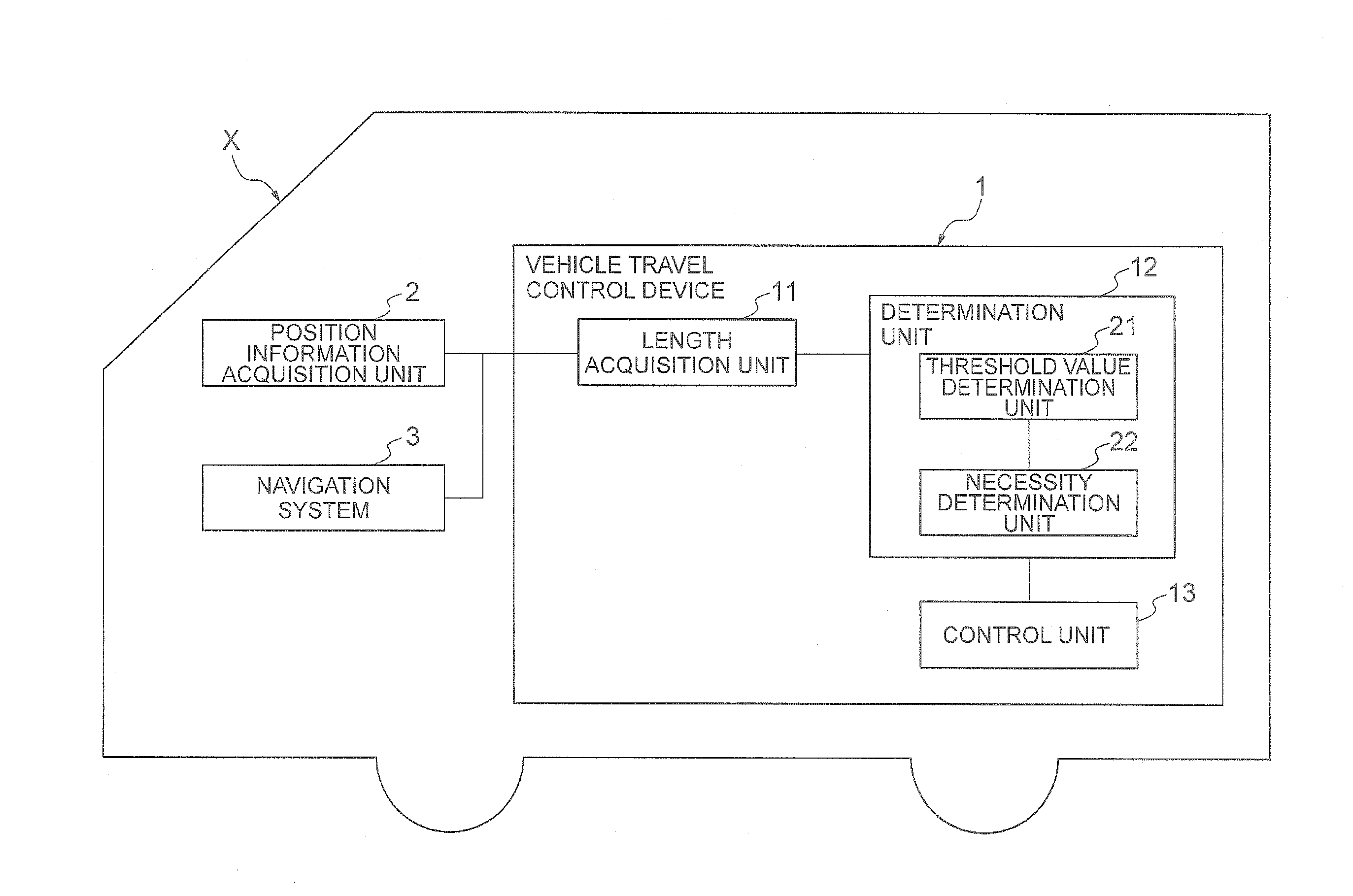
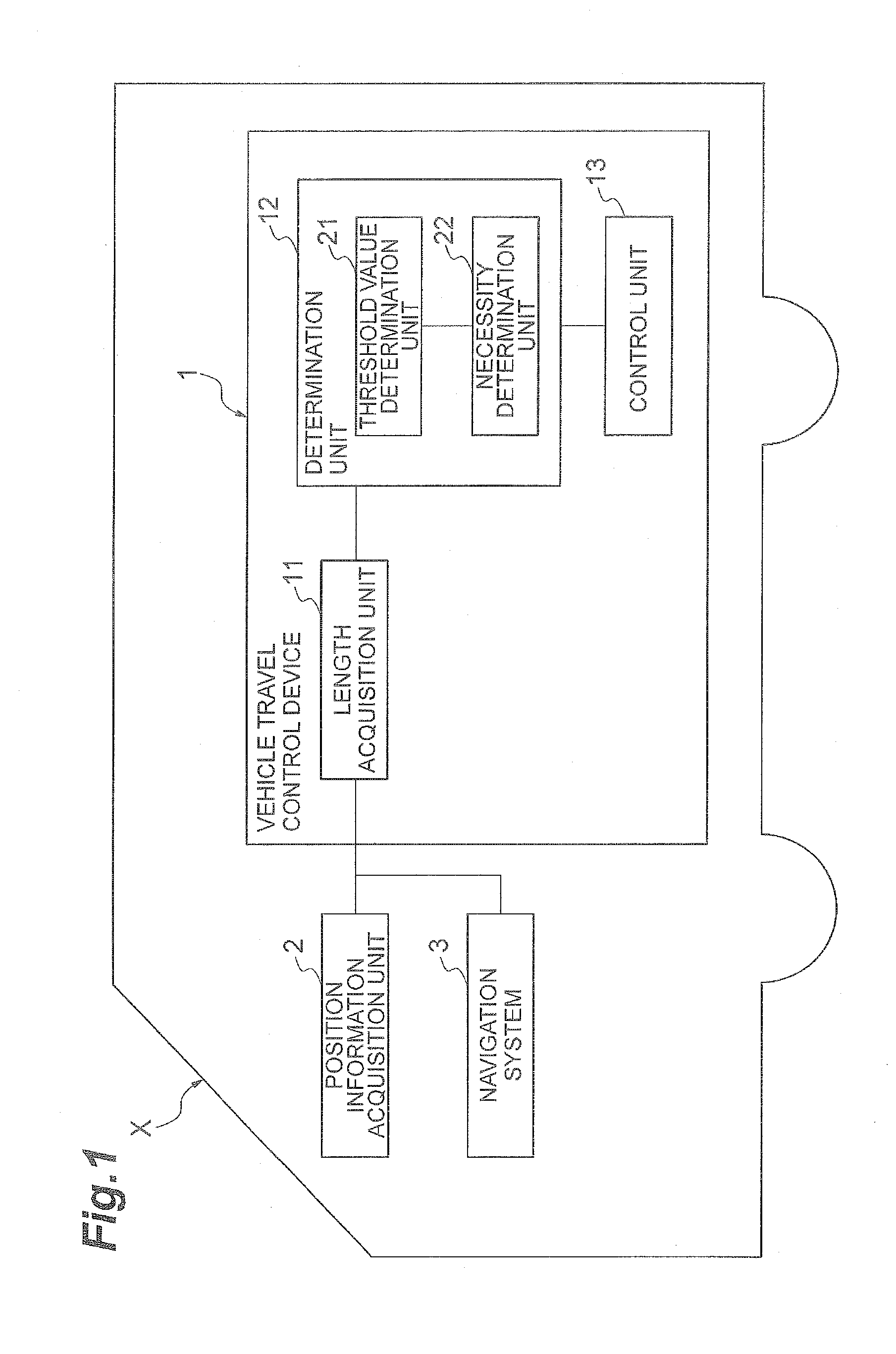
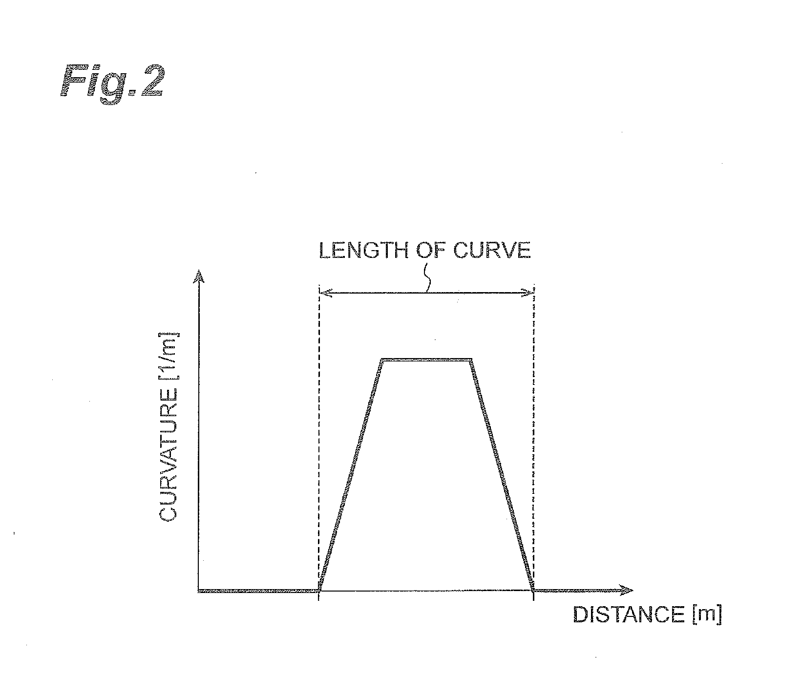
[0025]A first embodiment will be described. As illustrated in FIG. 1, a vehicle travel control device 1, a position information acquisition unit 2, and a navigation system 3 are included in a vehicle X. The position information acquisition unit 2 acquires position information of the vehicle X. As the position information acquisition unit 2, for example, a global positioning system (GPS) can be used. The navigation system 3 stores map information. A position where a road is installed and a curvature of the road are included in the map information. In addition, for example, a width of a lane may be included in the map information. As the curvature of the road, curvature values are associated with the road for each predetermined distance on the map information. The curvature of the road is, for example, a curvature at the center of a travelling road in the width direction (as an example, the curvature at a center line of the travelling road). The navigation system 3 can provide informa...
second embodiment
[0046]A second embodiment will be described. As illustrated in FIG. 6, the vehicle travel control device 1A in the second embodiment is configured to include a length acquisition unit 11, a determination unit 12A, a control unit 13, and a cant acquisition unit 14. In the vehicle travel control device 1A in the second embodiment, a determination method of the threshold value used in determining the necessity of deceleration control is mainly different from the method in the vehicle travel control device 1 in the first embodiment.
[0047]The cant acquisition unit 14 acquires a cant (horizontal slope) in the curve in front of the vehicle X. In the present embodiment, a direction of the cant of the road and the cant value of the road are also included in the map information stored in the navigation system 3 in addition to the position where the road is provided and the curvature of the road. The direction of the cant and the cant value of the road are associated with each other, for examp...
third embodiment
[0054]A third embodiment will be described. As illustrated in FIG. 9, a vehicle travel control device 1B in the third embodiment is configured to include a length acquisition unit 11, a determination unit 12B, a control unit 13, and a vertical gradient acquisition unit 15. In the vehicle travel control device 1B in the third embodiment, a determination method of the threshold value used in determining the necessity of deceleration control is mainly different from the method in the vehicle travel control device 1 in the first embodiment.
[0055]The vertical gradient acquisition unit 15 acquires a vertical gradient in the curve in front of the vehicle X. In the present embodiment, a direction of the vertical gradient and the vertical gradient value of the road are also included in the map information stored in the navigation system 3 in addition to the position where the road is provided and the curvature of the road. In the vertical gradient of the road, the direction of the vertical g...
PUM
 Abstract
Description
Claims
Application Information
 - R&D
- Intellectual Property
- Life Sciences
- Materials
- Tech Scout
- Unparalleled Data Quality
- Higher Quality Content
- 60% Fewer Hallucinations
Browse by: Latest US Patents, China's latest patents, Technical Efficacy Thesaurus, Application Domain, Technology Topic, Popular Technical Reports.
© 2025 PatSnap. All rights reserved.Legal|Privacy policy|Modern Slavery Act Transparency Statement|Sitemap|About US| Contact US: help@patsnap.com


