Turbine blade cooling structure

a cooling structure and turbine blade technology, applied in the direction of engine fuction, machine/engine, engine manufacturing, etc., can solve the problems of unsatisfactory cooling effect, non-uniform temperature distribution in the cooling medium, engine efficiency degradation, etc., to achieve sufficient cooling effect, reduce engine efficiency, and simplify the cooling structure

Active Publication Date: 2016-04-28
KAWASAKI HEAVY IND LTD +1
View PDF20 Cites 8 Cited by
  • Summary
  • Abstract
  • Description
  • Claims
  • Application Information

AI Technical Summary

Benefits of technology

[0008]Therefore, an object of the present invention is to provide, in order to solve the above-described problem, a cooling structure capable of cooling a turbine blade with high efficiency by achieving uniform temperature distribution of a cooling medium that passes through a cooling passage in the turbine blade.
[0010]According to the above configuration, the cooling medium, which is supplied from the portion of the cooling medium passage that includes the peripheral wall to the cooling medium passage, separately flows into the plurality of cylindrical spaces, and forms swirling flows in the respective cylindrical spaces. Further, a portion of each swirling flow in one of the cylindrical spaces flows into the other cylindrical space through an overlapped region of the spaces. Thus, when the swirling flows of the cooling medium formed in the adjacent cylindrical spaces flow into the opposite cylindrical spaces, mixing of the cooling medium is promoted, and temperature distribution in the cooling medium is made uniform, resulting in high cooling efficiency. Furthermore, when each swirling flow in one cylindrical space flows into the other cylindrical space, the swirling flow collides against a partition edge formed between the cylindrical spaces, whereby high cooling effect due to impingement effect is achieved.
[0011]In one embodiment of the present invention, the two cylindrical spaces adjacent to each other may overlap each other such that an overlap length W along a straight line connecting centers of cross-sectional circles of the adjacent two cylindrical spaces satisfies a relationship of 0.05≦W / ((D1+D2) / 2)≦0.35 with respect to a cross-sectional diameter D1 of one of the cylindrical spaces and a cross-sectional diameter D2 of the other cylindrical space. By setting the degree of overlapping of the cylindrical spaces in this way, it is possible to reliably cause a phenomenon in which separated swirling flows are generated in the respective cylindrical spaces, and each swirling flow in one cylindrical space flows into the other cylindrical space.
[0012]In one embodiment of the present invention, the cooling medium supply passage to supply the cooling medium to the cooling medium passage may be connected to the overlapped region of the adjacent two cylindrical spaces of the cooling medium passage. In this case, the cooling medium supply passage may be connected to the overlapped region such that the cooling medium supplied from the cooling medium supply passage collides against a partition edge formed between the adjacent two cylindrical spaces. In this configuration, since the cooling medium supplied from the cooling medium supply passage collides against the partition edge formed between the cylindrical spaces, the cooling medium is substantially uniformly distributed to the cylindrical spaces, whereby swirling flows in opposite directions, each having high directivity, are formed along the inner wall surfaces forming the cylindrical spaces. As a result, mixing of the cooling medium is further promoted. Further, also in the cooling medium supplying portion, the cooling medium may be caused to collide against the partition edge, whereby cooling of the wall surface is promoted due to the impingement effect. These effects result in extremely high cooling efficiency.
[0013]In one embodiment of the present invention, the cooling medium supply passage to supply the cooling medium to the cooling medium passage may be connected to a side portion of the cooling medium passage, located at a side opposite to the overlapped region of the cylindrical spaces, on the straight line connecting the centers of the cross-sectional circles of the adjacent two cylindrical spaces of the cooling medium passage. This configuration allows flexible design according to the shape of the portion of the turbine blade to which the cooling structure is applied.

Problems solved by technology

On the other hand, when a large amount of air compressed by the compressor is used for cooling the turbine blade, efficiency of the engine is degraded.
In this case, temperature distribution in the cooling medium is non-uniform, and sufficient cooling effect cannot be achieved.

Method used


Image

  • Turbine blade cooling structure
  • Turbine blade cooling structure
  • Turbine blade cooling structure

Examples


first embodiment

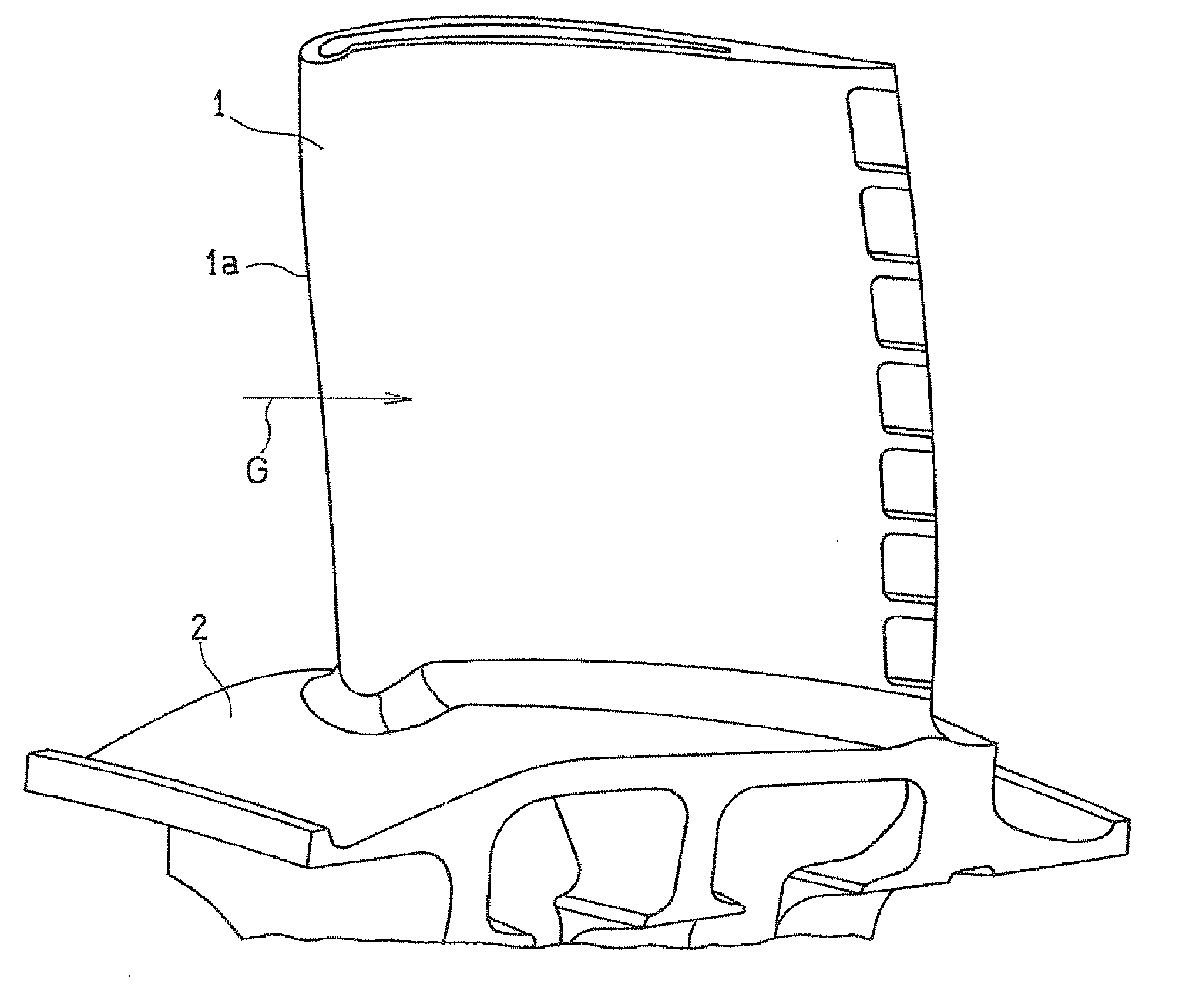
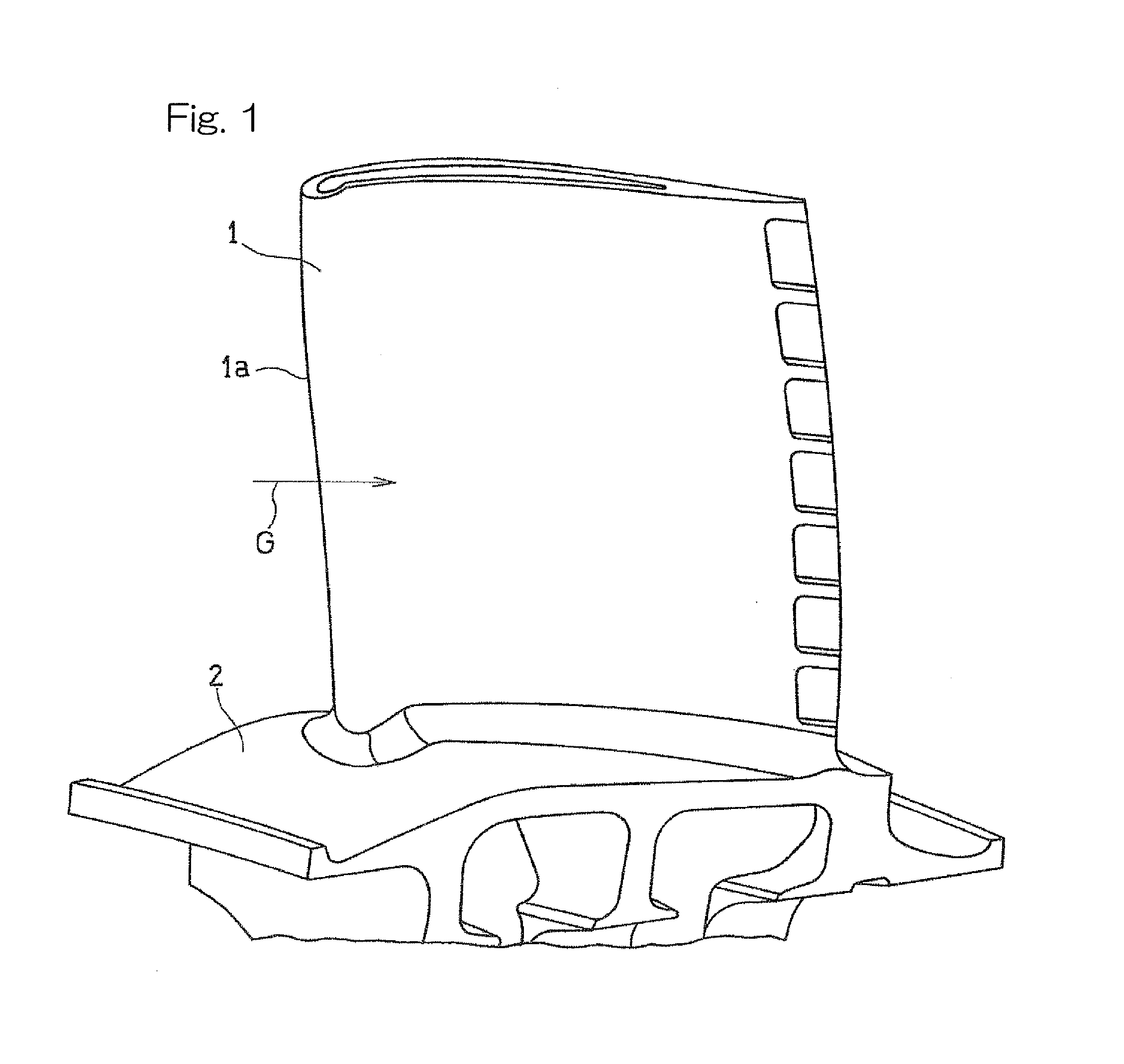
[0027]Hereinafter, embodiments of the present invention will be described with reference to the drawings. FIG. 1 is a perspective view showing a rotor blade 1 which is a turbine blade of a turbine of a gas turbine engine, to which a turbine blade cooling structure according to the present invention is applied. Many turbine rotor blades 1 are implanted in a circumferential direction of a turbine disk, with platforms 2 thereof being connected to an outer peripheral portion of a turbine disk, thereby forming a turbine. Each turbine rotor blade 1 is exposed to a high-temperature gas G that is supplied from a combustor and flows in a direction indicated by the arrow. In the following description, an upstream side (left side in FIG. 1) along the flow direction of the high-temperature gas G is referred to as “front”, and a downstream side (right side in FIG. 1) is referred to as “rear”. In this embodiment, the cooling structure is applied to the inside of a front end portion 1a of the turb...

third embodiment

[0039]The number of cylindrical spaces forming the first cooling medium passage 5 is not limited to two. As the present invention, as shown in FIGS. 9A and 9B, for example, three cylindrical spaces S1, S2, and S3 may be arrange in order so that the adjacent cylindrical spaces S1 and S2 overlap each other and the adjacent cylindrical spaces S2 and S3 overlap each other. In this case, as shown in FIG. 9A, the first cooling medium passage 5 may have a shape in which the three cylindrical spaces S1 to S3 are arranged in a substantially straight line (that is, centers O1, O2, and O3 of cross-sectional circles C1, C2, and C3 are in the same straight line). Alternatively, in accordance with the shape of a portion of a turbine blade to which the cooling structure is applied, as shown in FIG. 9B, the first cooling medium passage 5 may have a shape in which a width direction X1 of the cylindrical spaces S1 and S2 and a width direction X2 of the cylindrical spaces S2 and S3 are not parallel wi...


PUM


Abstract

In a structure for internally cooling a turbine blade, a cooling medium passage is provided in the turbine blade. The cooling medium passage has a shape in which a plurality of cylindrical spaces, each having substantially cylindrical shape, extending in parallel with each other partially overlap each other. A cooling medium supply passage that supplies a cooling medium to the cooling medium passage is connected to a portion of the cooling medium passage that includes a peripheral wall, in a direction that forms an acute angle with respect to a longitudinal direction of the cooling medium passage.

Description

CROSS REFERENCE TO THE RELATED APPLICATION[0001]This application is a continuation application, under 35 U.S.C. §111(a), of international application No. PCT / JP2014 / 062992, filed May 15, 2014, which claims priority to Japanese patent application No. 2013-105818, filed May 20, 2013, the disclosure of which are incorporated by reference in their entirety into this application.BACKGROUND OF THE INVENTION[0002]1. Field of the Invention[0003]The present invention relates to a structure for internally cooling a turbine blade of a turbine of a gas turbine engine.[0004]2. Description of Related Art[0005]Since a turbine as a component of a gas turbine engine is disposed downstream of a combustor and is supplied with a high-temperature gas burned in the combustor, the turbine is exposed to high temperature while the gas turbine engine is driven. Therefore, turbine blades, i.e., a stator blade and a rotor blade of the turbine, need to be cooled. As a structure for cooling such turbine blades, ...

Claims


Application Information

Patent Timeline
Patent Type & Authority Applications(United States)
IPC IPC(8): F01D5/18
CPCF05D2260/201F01D5/187F05D2240/303F05D2250/141F05D2250/15F05D2250/231F05D2250/25F05D2250/312F05D2250/314F05D2250/72F05D2260/2212F05D2260/2214
Inventor TANIGUCHI, TOMOKITANAKA, RYOZOHORIUCHI, TAKESHISUGIMOTO, TAKAOKAZARI, MASAHIDEKUSTERER, KARSTENBOHN, DIETERLIN, GANG
Owner KAWASAKI HEAVY IND LTD
Why Eureka
Try Eureka