System and method for adaptive rotor imbalance control

a technology of imbalance control and adaptive rotor, which is applied in the direction of rotors, vessel construction, marine propulsion, etc., can solve the problems of tower oscillation or vibration, disadvantageously induced tower oscillation, and oscillation in the tower

Active Publication Date: 2016-04-28
GENERAL ELECTRIC CO
View PDF4 Cites 16 Cited by
  • Summary
  • Abstract
  • Description
  • Claims
  • Application Information

AI Technical Summary

Problems solved by technology

Tower oscillations or vibrations occur due to various disturbances, such as turbulence, inefficient damping, or transition between the two wind conditions.
Such continuous variation in wind force may induce oscillations in the tower.
Because of this independence, the currently available rotor velocity control loops may compute a pitch angle to maintain rotor speed that may disadvantageously induce tower oscillations instead of reducing them.
Moreover, these rotor velocity control loops may cause energy amplification in the rotor near tower resonance frequencies.
Such amplification may increase oscillations in the tower and increase the fatigue load placed on the wind turbine.
Over time, such fatigue loads may reduce the life of wind turbine parts and increase the expenses associated with wind turbines.
Positive wind shear tends to bend the rotor up, and usually is present (high cycle fatigue) and increases with increasing wind speed.
The wind shear applies an asymmetric load across the rotor which results in a bending moment being transferred to the hub / shaft.
There is a limit on the amount of pitching the turbine is able to do to either overcome blade / hub forces or to compensate for gravity.
When the shear controller is in a limit, it is also not able to respond to additional steady state or dynamic (relatively fast changes in shear).
Imbalance load limitations such as environmental conditions including shear, gravity, turbulence, wind miss-alignments, etc., result in environmentally induced rotor imbalance.
Other forms of rotor imbalance are self-induced due to control, manufacturing, and installation variation.

Method used


Image

  • System and method for adaptive rotor imbalance control
  • System and method for adaptive rotor imbalance control
  • System and method for adaptive rotor imbalance control

Examples


Embodiment Construction

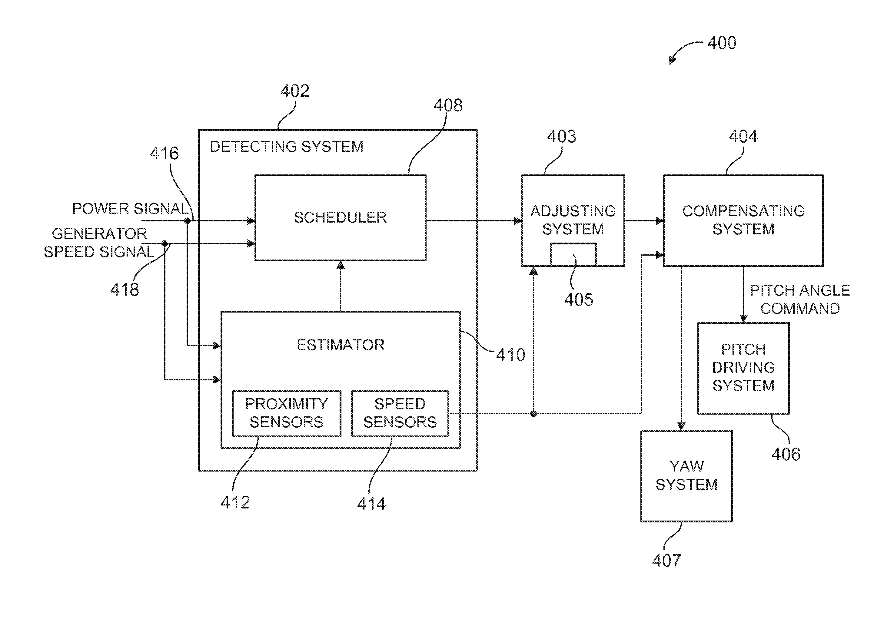
[0020]As will be described in detail hereinafter, various embodiments of an exemplary wind turbine control system and method for adjusting the shaft moment set point correction value in an operating wind turbine are presented. By employing the methods and the various embodiments of the wind turbine control system described hereinafter, the shaft moment set point correction value may be adjusted based on at least one of wind shear, wind speed, and load imbalance due to wind shear. Also, the wind turbine control system may help in reducing wear and tear on pitch control components, which in turn reduces the cost of energy.

[0021]Pitching of the rotor blades is desired for lower loads and higher annual energy production (AEP). However, rotor imbalance control is designed to track a fixed value of shaft moment set point. This value is set once and never changed. In reality, this set point is not optimal for every value of wind shear. As the wind shear varies, the rotor imbalance control ...


PUM


Abstract

A control system for a wind turbine includes a detecting system configured to determine at least one of a rotor load, a wind shear, a wind speed, and a load imbalance due to wind shear. An adjusting system is configured to adjust a shaft moment set point correction value based on at least one of the rotor load, the wind shear, the wind speed, and the load imbalance. A compensating system is configured to compute a shaft moment correction command based on the shaft moment set point correction value output from the adjusting system. A pitch system is configured to adjust a pitch of at least one blade of the wind turbine based on the shaft moment set point correction command, or a yaw system is configured to adjust the yaw position of a rotor based on the shaft moment set point correction command.

Description

BACKGROUND OF THE INVENTION[0001]The disclosure relates generally to a wind turbine and more specifically to a system and method for adjusting the shaft moment set point correction based on environmental conditions resulting in wind turbine load imbalance.[0002]Modern wind turbines operate in a wide range of wind conditions. These wind conditions can be broadly divided into two categories, below rated speeds and above rated speeds. To produce power in these wind conditions, wind turbines may include sophisticated control systems such as pitch controllers and torque controllers. These controllers account for changes in the wind conditions and accompanying changes in wind turbine dynamics. For example, pitch controllers (or pitch systems) generally vary the pitch angle of rotor blades to account for (or adapt to) the changes in wind conditions and turbine dynamics. During below rated wind speeds, wind power may be lower than the rated power output of the wind turbine. In this situatio...

Claims


Application Information

Patent Timeline
Patent Type & Authority Applications(United States)
IPC IPC(8): F03D7/04F03D11/00F03D7/02
CPCF03D7/046F03D11/0091F03D7/0224F03D7/0296F03D7/024F03D7/0204Y02E10/72F03D17/00
Inventor MARWAHA, MONIKAGERBER, BRANDON SHANEGANDHI, JIGNESH GOVINDLALCARDINAL, MARK EDWARDPERLEY, THOMAS FRANKLIN
Owner GENERAL ELECTRIC CO
Why Eureka
Try Eureka