
Test bench combining high-frequency tribological stress and oligocyclic fatigue

a tribological stress and oligocyclic fatigue technology, applied in the field of test rigs, can solve the problems of not being able to combine stresses, and being difficult to achieve the effect of combining stresses and simple, effective and economical effects

Active Publication Date: 2016-04-28
SN DETUDE & DE CONSTR DE MOTEURS DAVIATION S N E C M A +1
View PDF2 Cites 2 Cited by
  • Summary
  • Abstract
  • Description
  • Claims
  • Application Information

AI Technical Summary

Benefits of technology

This patent proposes a new test rig for a blade-disc attachment used in powered flight. The rig can combine both slow and fast cycles of vibration, as well as sliding between bearing surfaces to represent the complex and high-frequency vibration modes of the blade. The rig can also try different temperatures to simulate real-use conditions. The invention's key technical feature is its ability to capture the vibration modes of the blade and to modify the natural modes of the attachment to sweep wide operating areas.

Problems solved by technology

The characterisation becomes very complex when tribological stress is added, such as for a blade-disc attachment.
Conventional fretting fatigue tests are carried out on test pieces having a standard geometry which are remote from the blade / disc attachment application and do not make it possible to combine the stresses described previously.
When the test means aim to reproduce a contact geometry similar to a blade-disc attachment, generally of the one-lobe type, said means are also limited in terms of combining the stresses.
Said test means are also not configured to combine low-cycle and high-cycle cycles at high temperature.
The test means from the prior art, even those dedicated to fretting fatigue and fatigue tests, thus do not make it possible to reliably analyse a turbine engine blade-disc attachment which is representative of an actual attachment in operating conditions.

Method used


Image

  • Test bench combining high-frequency tribological stress and oligocyclic fatigue
  • Test bench combining high-frequency tribological stress and oligocyclic fatigue
  • Test bench combining high-frequency tribological stress and oligocyclic fatigue

Examples


Embodiment Construction

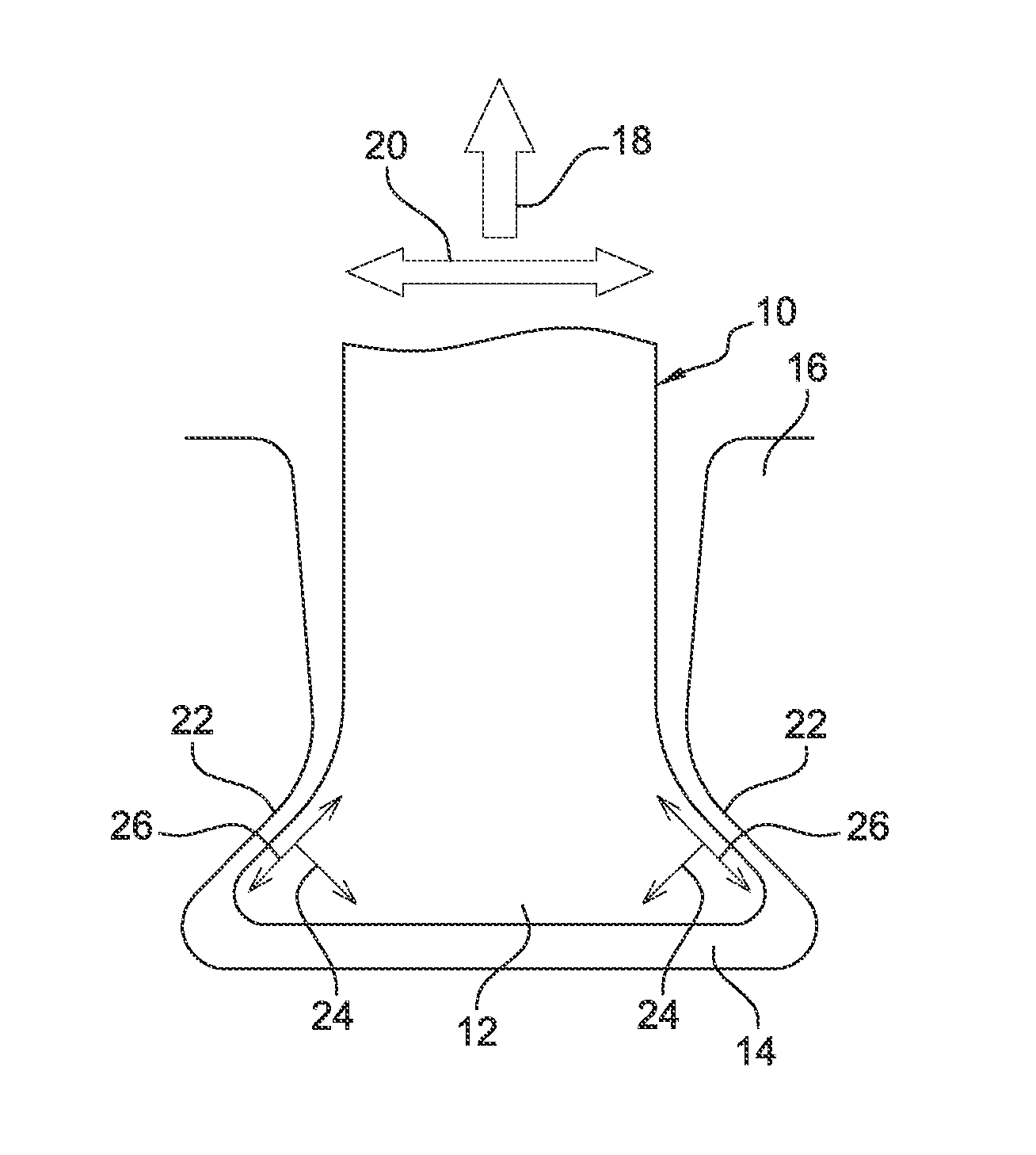
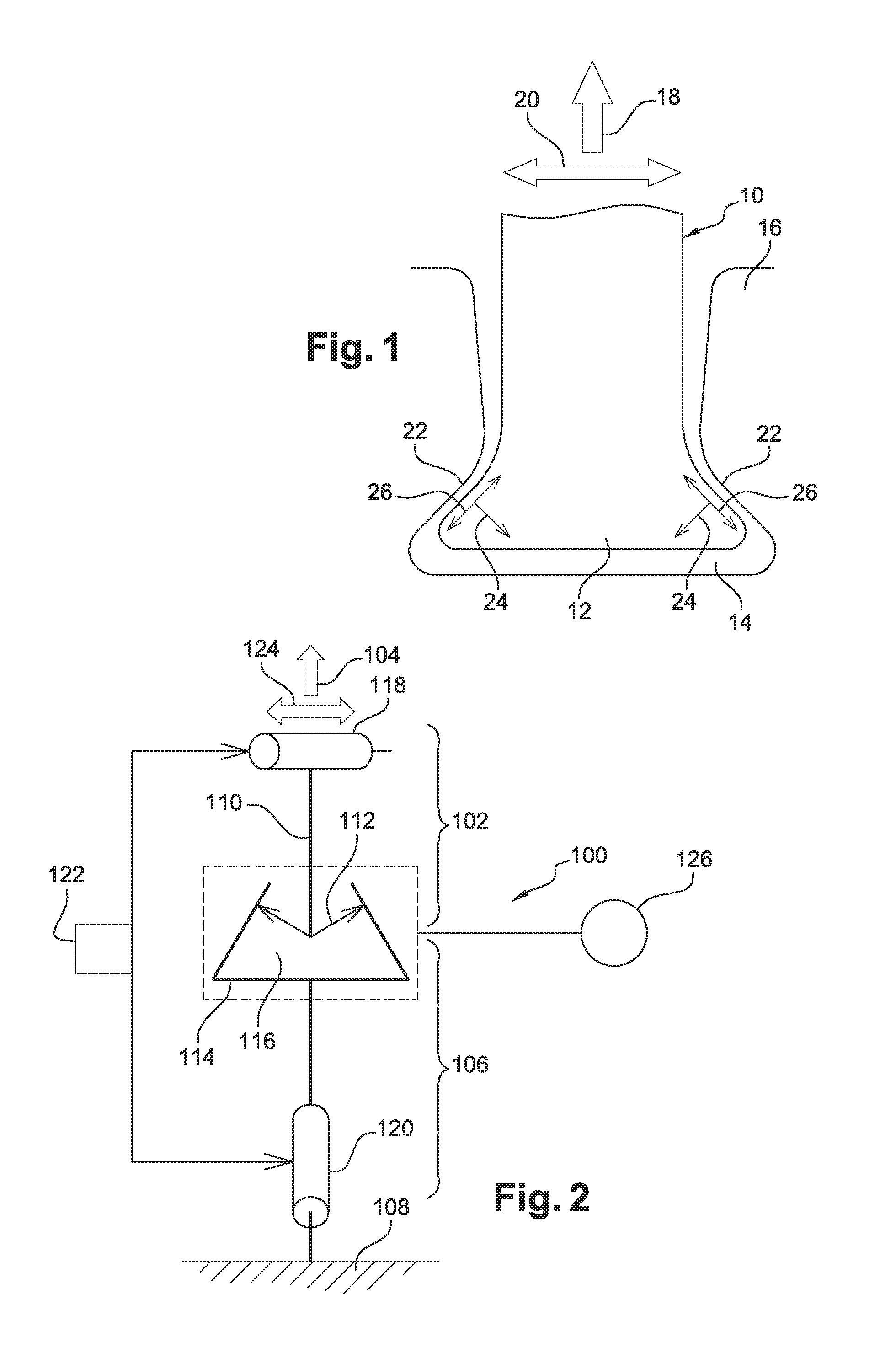
[0035]Reference is firstly made to FIG. 1, which schematically shows a blade-disc attachment of a turbine engine, the blade 10 being a rotor blade comprising a root 12 which is inserted in a groove 14 in the periphery of a disc 16, said disc comprising an annular array of grooves 14 of this type for receiving the roots of a plurality of blades. The assembly formed by the disc 16 and the blades 10 form a rotor wheel for example of a turbine of the turbine engine. In this case, the root 12 is of the dovetail type.

[0036]During operation, the blade 10 is subjected to centrifugal forces (arrow 18) and the vane thereof has a tendency to oscillate (arrow 20), causing the lateral portions, referred to as threads of the blade root 12, to bear and slide against lateral projections 22 of the groove 14 in the disc. The arrows 24 show normal forces which are applied to the surfaces facing the blade root 12 and the groove 14, and the arrows 26 denote shearing forces which are applied to said surf...


PUM

PropertyMeasurementUnit
temperatureaaaaaaaaaa
frequencyaaaaaaaaaa
frequenciesaaaaaaaaaa

Abstract

Test rig combining high-frequency tribological stress and low-cycle fatigue, comprising a first test piece which is fixed to a frame and defines at least one bearing surface, a second test piece which is connected to traction means for loading the second test piece so that it bears against the or each bearing surface of the first test piece, means for heating the test pieces and means for loading the test pieces in a vibratory manner so as to carry out a fretting fatigue and low-cycle and high-cycle fatigue test, one of the test pieces comprising a portion which is in the shape of a turbine engine rotor blade root and which is inserted in a groove, the shape of which groove is substantially complementary to the other test piece so as to reproduce a turbine engine blade-disc attachment.

Description

TECHNICAL FIELD[0001]The present invention relates to a test rig combining high-frequency tribological stresses and low-cycle fatigue, also known by the name fretting fatigue test, said test rig being intended to reproduce a turbine engine blade-disc attachment.PRIOR ART[0002]Numerous turbine engine parts are subjected to complex stresses superimposing high-cycle (vibratory) and low-cycle stresses. The characterisation becomes very complex when tribological stress is added, such as for a blade-disc attachment.[0003]This is the case for a turbine blade, which is loaded with a centrifugal force due to the rotation of the turbine, a vibratory force due to the environment and the resonating thereof. These two stresses lead to sliding of the blade root against the lateral projections of the recess in the disc, in which recess the blade root is inserted. Knowledge of this tribological aspect is essential because the blade root is then subjected to fretting fatigue damage. This field of st...

Claims


Application Information

Patent Timeline
Patent Type & Authority Applications(United States)
IPC IPC(8): G01N3/32
CPCG01N3/32G01N2203/0005G01N2203/0073G01N2203/0226G01N2203/027
Inventor HOUZE, LAURENTLAPUYADE, JEAN PHILIPPEVERNIS, FRANCKVOGEL, FRANCOISMERIAUX, JEAN VINCENT MANUEL
Owner SN DETUDE & DE CONSTR DE MOTEURS DAVIATION S N E C M A
Learn More