Light emitting element driving device, light emitting device, and vehicle

a technology of light emitting devices and driving devices, which is applied in the direction of electroluminescent light sources, transportation and packaging, electric lighting sources, etc., can solve the problem of short circuit similar to a ground fault due to abnormality formed by short-circuiting switches

Active Publication Date: 2016-05-05
ROHM CO LTD
View PDF0 Cites 19 Cited by
  • Summary
  • Abstract
  • Description
  • Claims
  • Application Information

AI Technical Summary

Benefits of technology

[0009]It is an object of the present invention to provide a light emitting element driving device that can prevent misdetection of a ground fault due to abnormality and p

Problems solved by technology

However, in the light emitting device including the series connected body constituted of a plurality of light emitting diodes, in which the number of turned-on light emitting diodes can be controlled by turning on and offthe short-circuiting switches, when the number of turned-on light emitting diodes is set to zero, a short circuit similar to a ground fault due to abnormality is formed by the short-circuiting switches.
For this reason, when the ground fault protection function is mounted in the ligh

Method used


Image

  • Light emitting element driving device, light emitting device, and vehicle
  • Light emitting element driving device, light emitting device, and vehicle
  • Light emitting element driving device, light emitting device, and vehicle

Examples


first embodiment

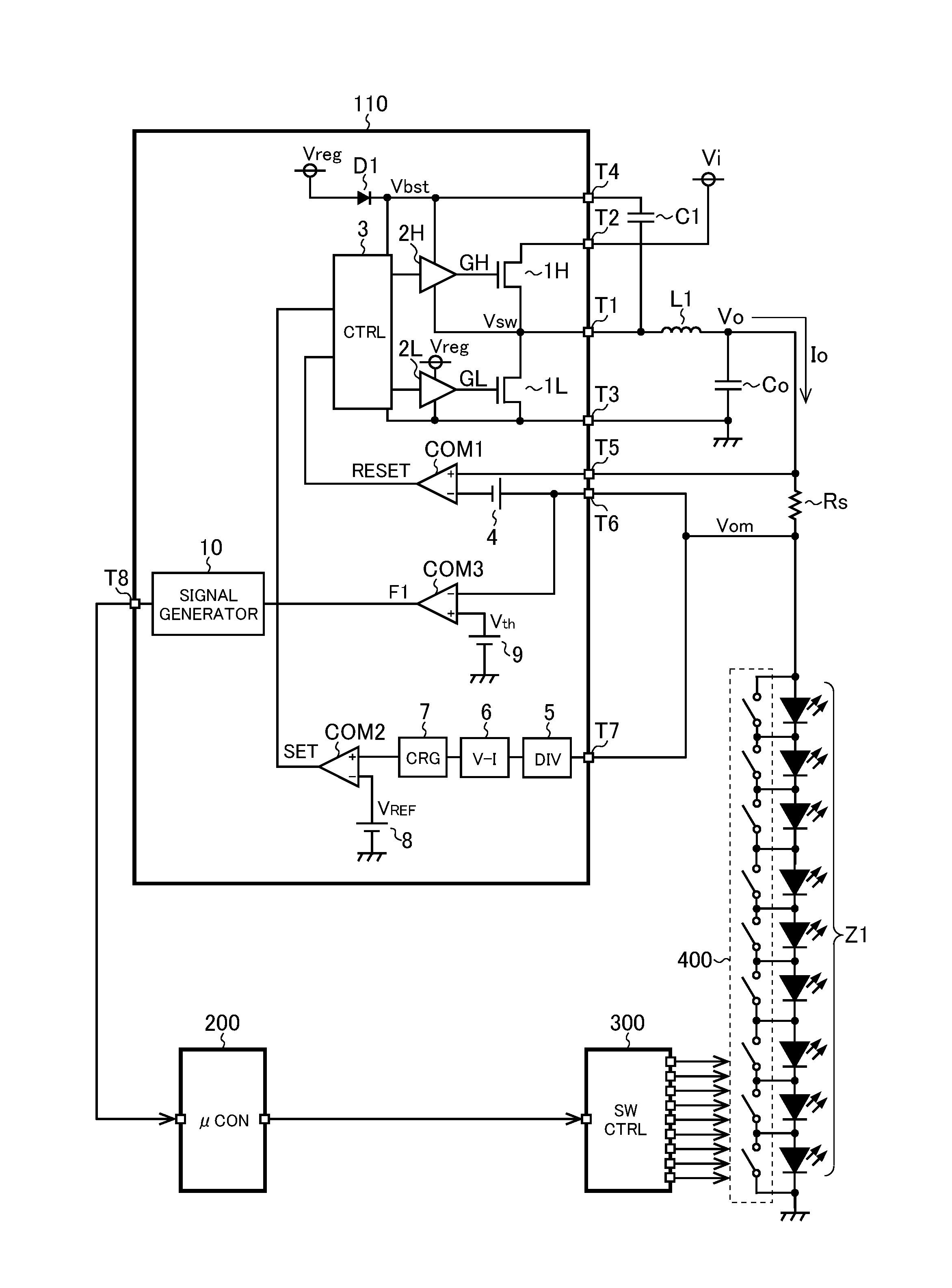
[0023]FIG. 1 is a diagram showing a light emitting device of a first embodiment. The light emitting device of the first embodiment includes a series connected body Z1 constituted of a plurality of light emitting elements (light emitting diodes in FIG. 1), a light emitting element driver IC 110 arranged to drive the series connected body Z1, a coil L1, an output capacitor Co, a sense resistor Rs, a capacitor C1, a microcomputer 200, a switch controller 300, and a switch circuit 400 constituted of short-circuiting switches disposed respectively in parallel with the light emitting elements of the series connected body Z1.

[0024]The light emitting element driver IC 110 is a semiconductor integrated circuit device (so-called LED driver IC) including an N-channel MOS field-effect transistors 1H and 1L (hereinafter referred to as an upper transistor 1H and a lower transistor 1L), an upper driver 2H and a lower driver 2L, a diode D1, a controller 3, constant voltage sources 4 and 9, comparat...

second embodiment

[0053]FIG. 5 is a diagram showing a light emitting device of a second embodiment. Note that in FIG. 5, the same part as in FIG. 1 is denoted by the same numeral, and detailed description thereof is omitted.

[0054]The light emitting device of the second embodiment has a structure in which the light emitting element driver IC 110 is replaced by a light emitting element driver IC 120 in the light emitting device of the first embodiment. The light emitting element driver IC 120 has a structure in which the constant voltage source 4 is replaced by a variable voltage source 4′ in the light emitting element driver IC 110.

[0055]The variable voltage source 4′ outputs an output voltage that is higher when the flag F1 is low level than when the flag F1 is high level. In this way, when the flag F1 is high level, the average value of the output current Io flowing in the load including the series connected body Z1 and the switch circuit 400 can be reduced. For instance, an output voltage of the va...

third embodiment

[0058]FIG. 6 is a diagram showing a light emitting device of a third embodiment. Note that in FIG. 6, the same part as in FIG. 5 is denoted by the same numeral, and detailed description thereof is omitted.

[0059]The light emitting device of the third embodiment has a structure in which the light emitting element driver IC 120 is replaced by a light emitting element driver IC 130 in the light emitting device of the second embodiment. The light emitting element driver IC 130 has a structure in which the constant voltage source 9 is replaced by a variable voltage source 9′ in the light emitting element driver IC 120.

[0060]A voltage output from the variable voltage source 9′ is adjusted to be lower than the anode voltage Vom of the load including the series connected body Z1 and the switch circuit 400 when only one of the light emitting diodes in the series connected body Z1 is turned on, and to be higher than the anode voltage Vom of the load including the series connected body Z1 and t...


PUM


Abstract

A light emission driving device includes an output voltage supply unit arranged to generate an output voltage from an input voltage so as to supply the output voltage to a load, a determination unit arranged to determine whether or not a ground fault due to abnormality may have occurred on the basis of an anode voltage of the load, and a signal output unit arranged to externally output a signal indicating that a ground fault due to abnormality may have occurred when the determination unit determines that a ground fault due to abnormality may have occurred. The output voltage supply unit does not perform generation stop of the output voltage by a trigger of determination by the determination unit that a ground fault due to abnormality may have occurred.

Description

CROSS-REFERENCE TO RELATED APPLICATIONS[0001]This nonprovisional application claims priority under 35 U.S.C. §119(a) on Patent Application No. 2014-225227 filed in Japan on Nov. 5, 2014, the entire contents of which are hereby incorporated by reference.BACKGROUND OF THE INVENTION[0002]1. Field of the Invention[0003]The present invention relates to a light emitting element driving device arranged to drive a light emitting element, and a light emitting device and a vehicle using the light emitting element driving device.[0004]2. Description of Related Art[0005]A light emitting device including a series connected body constituted of a plurality of light emitting diodes is used for a headlight of a vehicle, for example. In order to realize an adaptive front-lighting system (AFS) or an adaptive driving beam (ADB) when the light emitting device is used for a headlight of a vehicle, it is preferred to dispose short-circuiting switches respectively in parallel with the light emitting elemen...

Claims


Application Information

Patent Timeline
IPC IPC(8): B60Q1/00H05B33/08H05B44/00
CPCB60Q1/0094H05B33/083H05B33/0896H05B33/089B60Q11/005H05B47/26H05B45/48H05B45/60
Inventor TAKAGIMOTO, SHINSUKENAKATANI, YOSHIYUKIKAWASE, SHIGENORI
Owner ROHM CO LTD
Why Eureka
Try Eureka