Methods of forming an improved via to contact interface by selective formation of a conductive capping layer
Active Publication Date: 2016-05-05
GLOBALFOUNDRIES US INC
8 Cites 10 Cited by
AI-Extracted Technical Summary
Problems solved by technology
Typically, due to the large number of circuit elements and the required complex layout of modern integrated circuits, the electrical connec...
Benefits of technology
[0015]The following presents a simplified summary of the invention in order to provide a basic understanding of some aspects of the invention. This summary is not an exhaustive overview of the invention. It is not intended to id...
Abstract
One illustrative method disclosed herein includes, among other things, forming an opening in a layer of insulating material so as to thereby expose at least a portion of a conductive contact, performing a selective deposition process to selectively form a layer of conductive material in the opening and on the conductive contact, performing an anneal process, depositing at least one conductive material above the selectively formed conductive material layer so as to over-fill the opening, and performing at least one planarization process so as to remove excess materials to thereby define a conductive via that is positioned in the opening and conductively coupled to the conductive contact.
Application Domain
Semiconductor/solid-state device detailsSolid-state devices +2
Technology Topic
Electrically conductiveConductive materials +2
Image
Examples
- Experimental program(1)
Example
[0023]While the subject matter disclosed herein is susceptible to various modifications and alternative forms, specific embodiments thereof have been shown by way of example in the drawings and are herein described in detail. It should be understood, however, that the description herein of specific embodiments is not intended to limit the invention to the particular forms disclosed, but on the contrary, the intention is to cover all modifications, equivalents, and alternatives falling within the spirit and scope of the invention as defined by the appended claims.
DETAILED DESCRIPTION
[0024]Various illustrative embodiments of the invention are described below. In the interest of clarity, not all features of an actual implementation are described in this specification. It will of course be appreciated that in the development of any such actual embodiment, numerous implementation-specific decisions must be made to achieve the developers' specific goals, such as compliance with system-related and business-related constraints, which will vary from one implementation to another. Moreover, it will be appreciated that such a development effort might be complex and time-consuming, but would nevertheless be a routine undertaking for those of ordinary skill in the art having the benefit of this disclosure.
[0025]The present subject matter will now be described with reference to the attached figures. Various structures, systems and devices are schematically depicted in the drawings for purposes of explanation only and so as to not obscure the present disclosure with details that are well known to those skilled in the art. Nevertheless, the attached drawings are included to describe and explain illustrative examples of the present disclosure. The words and phrases used herein should be understood and interpreted to have a meaning consistent with the understanding of those words and phrases by those skilled in the relevant art. No special definition of a term or phrase, i.e., a definition that is different from the ordinary and customary meaning as understood by those skilled in the art, is intended to be implied by consistent usage of the term or phrase herein. To the extent that a term or phrase is intended to have a special meaning, i.e., a meaning other than that understood by skilled artisans, such a special definition will be expressly set forth in the specification in a definitional manner that directly and unequivocally provides the special definition for the term or phrase.
[0026]The present disclosure is directed to various methods of forming an improved interface between a conductive via and a conductive contact structure. As will be readily apparent to those skilled in the art upon a complete reading of the present application, the methods disclosed herein may be employed when forming conductive structures that contact a variety of different semiconductor devices, e.g., transistors, memory cells, resistors, etc., and may be employed when forming conductive structures for a variety of different integrated circuit products, including, but not limited to, ASIC's, logic devices, memory devices, etc. With reference to the attached drawings, various illustrative embodiments of the methods disclosed herein will now be described in more detail.
[0027]FIGS. 2A-2E depict one illustrative method disclosed herein for forming an improved interface between a conductive via and a conductive contact structure by selective formation of a conductive capping layer. FIG. 2A depicts the device 100 at a point in processing that corresponds to that depicted in FIG. 1F. The substrate may have a variety of configurations, such as a bulk substrate configuration, an SOI (silicon-on-insulator) configuration, and it may be made of materials other than silicon. Thus, the terms “substrate” or “semiconductor substrate” should be understood to cover all semiconducting materials and all forms of such materials. The device 100 may be any type of integrated circuit device that employs any type of a conductive structure, such as a contact or a conductive line or via, commonly found on integrated circuit devices. The conductive structures depicted, described and claimed in this application are intended to be representative in nature as they may represent any type of conductive feature or structure on an integrated circuit product. In the examples depicted herein, the conductive structures are depicted as having a representative barrier and/or adhesion layer. In practice, there may be one or more such barrier/adhesion layers used in a real-world device. The conductive structures described and discussed herein may be made of any type of conductive material, e.g., a metal or a metal alloy, such as copper or a copper-based material.
[0028]FIG. 2B depicts the device 100 after a selective deposition process was performed to selectively form a layer of conductive material 102A on the contact 32. As depicted, the selectively formed layer of conductive material 102A may only partially fill the seam 31. In one embodiment, the selectively formed layer of conductive material 102A may be comprised of a material such as cobalt, nickel, etc., it may be formed by performing a selective conformal chemical vapor deposition (CVD) process, and it may be formed to any desired thickness, e.g., 0.5-5 nm. During this selective deposition process 102, substantially none of the selectively formed layer of conductive material 102A is formed on the layers of insulating materials openings 41, considering the entire height of the opening 41 as it extends through the multiple layers of insulating material. The manner in which the selective formation of such materials may be accomplished is well known to those skilled in the art. For example, see “Characterization of Selectively Deposited Cobalt Capping Layers: Selectivity and Electromigration Resistance,” Yang et al., IEEE Electron Device Letters, Vol. 31, No. 7, Jul. 2010, which is hereby incorporated by reference in its entirety.
[0029]FIG. 2C depicts the device 100 after an anneal process 104 was performed on the device 100. In one embodiment, the anneal process may be performed at a temperature that falls within the range of about 200-400° C. for a duration of about 1-60 minutes. The anneal process 104 may be a laser anneal process, an RTA process, etc. In the case where the selectively formed layer of conductive material 102A is made of cobalt, the cobalt material has a relatively low melting point. Thus, the cobalt material, when heated, will move to substantially fill at least the upper portion of any remaining unfilled portions of the seam or void 31, as indicated in the dashed line regions 106. In some cases, performing the anneal process 104 may cause the selectively formed layer of conductive material 102A to fill substantially all of the void 31. In some applications, selective formation of the layer of conductive material 102A may actually completely fill at least the upper portion of the void 31, or the entire void 31, prior to the anneal process 104 being performed. However, performing the anneal process 104 described herein insures that substantially all of the void 31, if present after the initial formation of the contact 32, or after formation of the layer of conductive material 102A, will be filled. In some applications, some of the millions of contacts 32 formed on an integrated circuit product may be initially formed without any voids therein. Nevertheless, the methods disclosed herein may still be performed to insure that any such voids 31, if present, may be addressed.
[0030]Next, as shown in FIG. 2D, a schematically depicted conductive barrier layer/adhesion layer 110 was formed across the device and in the openings 41. The conductive barrier layer/adhesion layer 110 is depicted with a dashed line so as to clearly distinguish it from the selectively formed layer of conductive material 102A. Of course, in practice, the barrier layer/adhesion layer 110 lines or covers the entire surface of the metallization openings 41. Then, an illustrative layer of bulk conductive material 112, e.g., copper, may be deposited in the openings 41 using traditional techniques. In the case where copper metallization layers will be formed for the device 100, the barrier layer/adhesion layer 110 may be comprised of a first barrier layer of tantalum nitride (TaN) (not separately shown in FIG. 2D) and a second adhesion layer (not separately shown in FIG. 2D) made of tantalum, both of which may be formed by performing sequential conformal deposition processes, e.g., ALD, PVD, etc. Other materials, such as cobalt and ruthenium, may be employed as part of the barrier layer/adhesion layer 110.
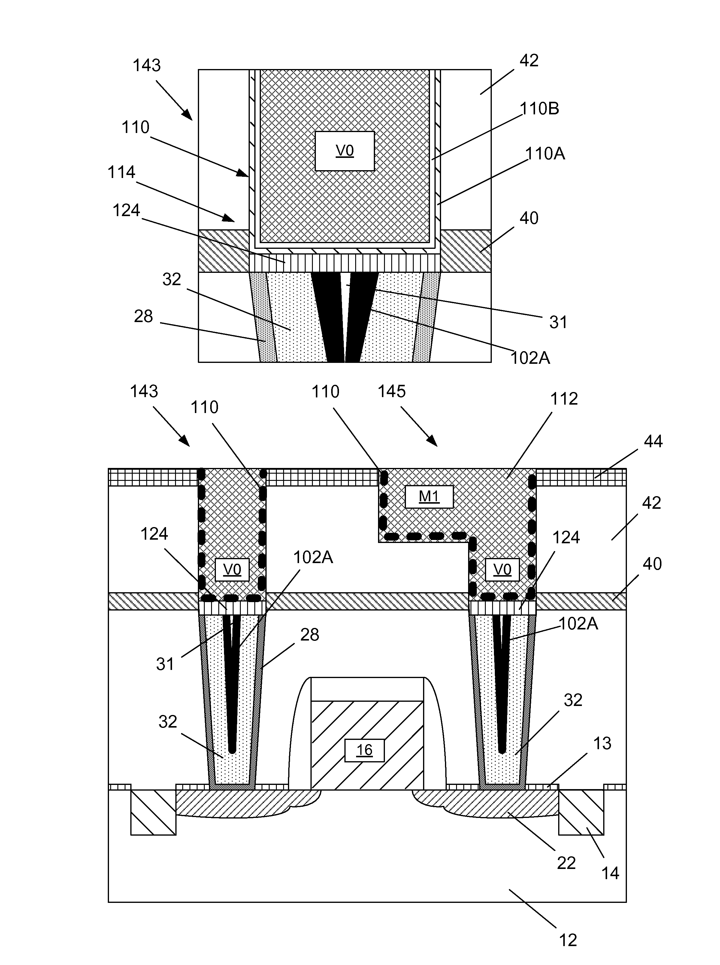
[0031]FIG. 2E depicts the device after one or more CMP process operations were performed to remove the excess materials positioned outside of the metallization openings 41 above the etch stop layer 44. This results in the formation of a conductive via 143 (VO) and a combination conductive via (VO)—metal line (M1) 145. FIG. 2E also contains an enlarged view of the novel interface 114 that may be formed using the methods disclosed herein. Also depicted are an illustrative barrier layer 110A and an illustrative adhesion layer 110B of the schematically depicted barrier layer and the adhesion layer 110. Note that the selective deposition process 102 is performed such that sidewalls of the openings 41 along an entire vertical height of the conductive via are substantially free of the selectively formed conductive material layer 102A. Due to the methods disclosed herein, the anneal process 104 is performed to insure that the void 31, if present, is filled prior to the formation of the barrier layer/adhesion layer 110. Accordingly, the barrier layer/adhesion layer 110 is positioned under the entirety of the conductive vias at the interface with the contacts 32, as indicated in the dashed-line regions 114. Thus, there is less likelihood of undesired copper migration using the methods disclosed herein, and the resistance of the connections may not be undesirably increased using the methods disclosed herein.
[0032]FIGS. 3A-3E depict yet another illustrative method disclosed herein for forming an improved interface between a conductive via and a conductive contact structure by selective formation of a metal silicide capping layer. FIG. 3A depicts the device 100 at a point in processing that corresponds to that depicted in FIG. 1F.
[0033]FIG. 3B depicts the device 100 after the above-described selective deposition process 102 was performed to selectively form the layer of conductive material 102A on the contacts 32. As depicted, the layer of conductive material 102A may only partially fill the upper portion of the seam 31. As before, the selective deposition process 102 is performed such that the sidewalls of the metallization openings 41 are substantially free of the selectively formed conductive material layer 102A.
[0034]FIG. 3C depicts the device 100 after a selective metal silicide formation process 120 was performed so as to selectively form metal silicide layers 124 on the contacts 32 within the openings 41. Note that the selective metal silicide formation process 120 is performed such that the sidewalls of the metallization openings 41 are substantially free of the selectively formed metal silicide layers 124. In one embodiment, the metal silicide layers 124 may be formed by introducing a silicon-containing precursor gas, such as silane (or another source of silicon) with a flow rate that falls within the range of about 1-1000 sccm, into a plasma environment that is at a temperature of less than, for example, 400° C. for a duration of about 1-60 seconds. As a result of volume expansion when the selectively formed metal silicide layers 124 are formed, at least the upper portions of the seams 31, to the extent present, will be substantially filled by the metal silicide layers 124. It is also possible that the seams 31 will be partially or entirely filled by the conductive material 102A. In the case where the selectively formed layer of conductive material 102A is cobalt, the selectively formed metal silicide layers 124 will be cobalt silicide. In one embodiment, the selectively formed metal silicide layers 124 may have a thickness of about 0.5-5 nm. During this selective metal silicide formation process 120, substantially none of the metal silicide layers 124 are formed on the layers of insulating materials within the metallization openings 41. The manner in which metal silicide layers may be selectively formed are well known to those skilled in the art. For example, see U.S. Pat. No. 4,822,642, which is hereby incorporated by reference in its entirety.
[0035]Next, as shown in FIG. 3D, the above-described conductive barrier layer/adhesion layer 110 and layer of conductive material 112 was formed across the device and in the openings 41.
[0036]FIG. 3E depicts the device after one or more CMP process operations were performed to remove the excess materials positioned outside of the openings 41 above the etch stop layer 44. This results in the formation of the above-described conductive via 143 (VO) and combination conductive via (VO)—metal line (M1) 145. In this embodiment, due to the formation of the selectively formed metal silicide layers 124, at least the upper portion of the void 31, if present, will be filled prior to the formation of the barrier layer/adhesion layer 110. FIG. 3E also contains an enlarged view of another novel interface 114 that may be formed using the methods disclosed herein. Also depicted are the above-described barrier layer 110A and adhesion layer 110B, as well as the selectively formed metal silicide layer 124. Accordingly, the barrier layer/adhesion layer 110 is positioned under the entirety of the conductive vias at the interface with the contacts 32, as indicated in FIG. 3E. Thus, there is less likelihood of undesired copper migration using the methods disclosed herein, and the resistance of the connections may not be undesirably increased using the methods disclosed herein. Note that the selective metal silicide formation process 120 was performed such that the sidewalls of the metallization openings 41 along an entire vertical height of the conductive via are substantially free of the selectively formed metal silicide layers 124.
[0037]The particular embodiments disclosed above are illustrative only, as the invention may be modified and practiced in different but equivalent manners apparent to those skilled in the art having the benefit of the teachings herein. For example, the process steps set forth above may be performed in a different order. Furthermore, no limitations are intended to the details of construction or design herein shown, other than as described in the claims below. It is therefore evident that the particular embodiments disclosed above may be altered or modified and all such variations are considered within the scope and spirit of the invention. Note that the use of terms, such as “first,”“second,”“third” or “fourth” to describe various processes or structures in this specification and in the attached claims is only used as a shorthand reference to such steps/structures and does not necessarily imply that such steps/structures are performed/formed in that ordered sequence. Of course, depending upon the exact claim language, an ordered sequence of such processes may or may not be required. Accordingly, the protection sought herein is as set forth in the claims below.
PUM


Description & Claims & Application Information
We can also present the details of the Description, Claims and Application information to help users get a comprehensive understanding of the technical details of the patent, such as background art, summary of invention, brief description of drawings, description of embodiments, and other original content. On the other hand, users can also determine the specific scope of protection of the technology through the list of claims; as well as understand the changes in the life cycle of the technology with the presentation of the patent timeline. Login to view more.