Light emitting module

a technology light emitting modules, which is applied in the direction of basic electric elements, electrical equipment, and semiconductor devices, etc., can solve the problems of uv rays emitted by uv leds that may discolor or alter other parts, uv rays may have a bad effect on reliability or durability of light emitting modules including uv leds, etc., to prevent discoloration

Active Publication Date: 2016-05-05
SUZHOU LEKIN SEMICON CO LTD
View PDF27 Cites 29 Cited by
  • Summary
  • Abstract
  • Description
  • Claims
  • Application Information

AI Technical Summary

Benefits of technology

[0011]If the light emitting module according to an embodiment is used, there is an advantage in that the adhesive member can be prevented from being discolored or altered due to heat or UV rays of the light source unit.
[0012]If the light emitting module according to an embodiment is used, there is an advantage in that a phenomenon in which any metal unstable in the first and second adhesive members adheres to the light-emitting surface of a light emitting device of the light source unit can be prevented when the cover and the body are coupled by eutectic bonding.

Problems solved by technology

In this case, the UV rays emitted by the UV LED may discolor or alter other parts including the body of a light emitting module.
The discoloration or alteration of the body or other parts attributable to UV rays may have a bad effect on reliability or durability of a light emitting module including an UV LED.

Method used


Image

  • Light emitting module
  • Light emitting module
  • Light emitting module

Examples


first embodiment

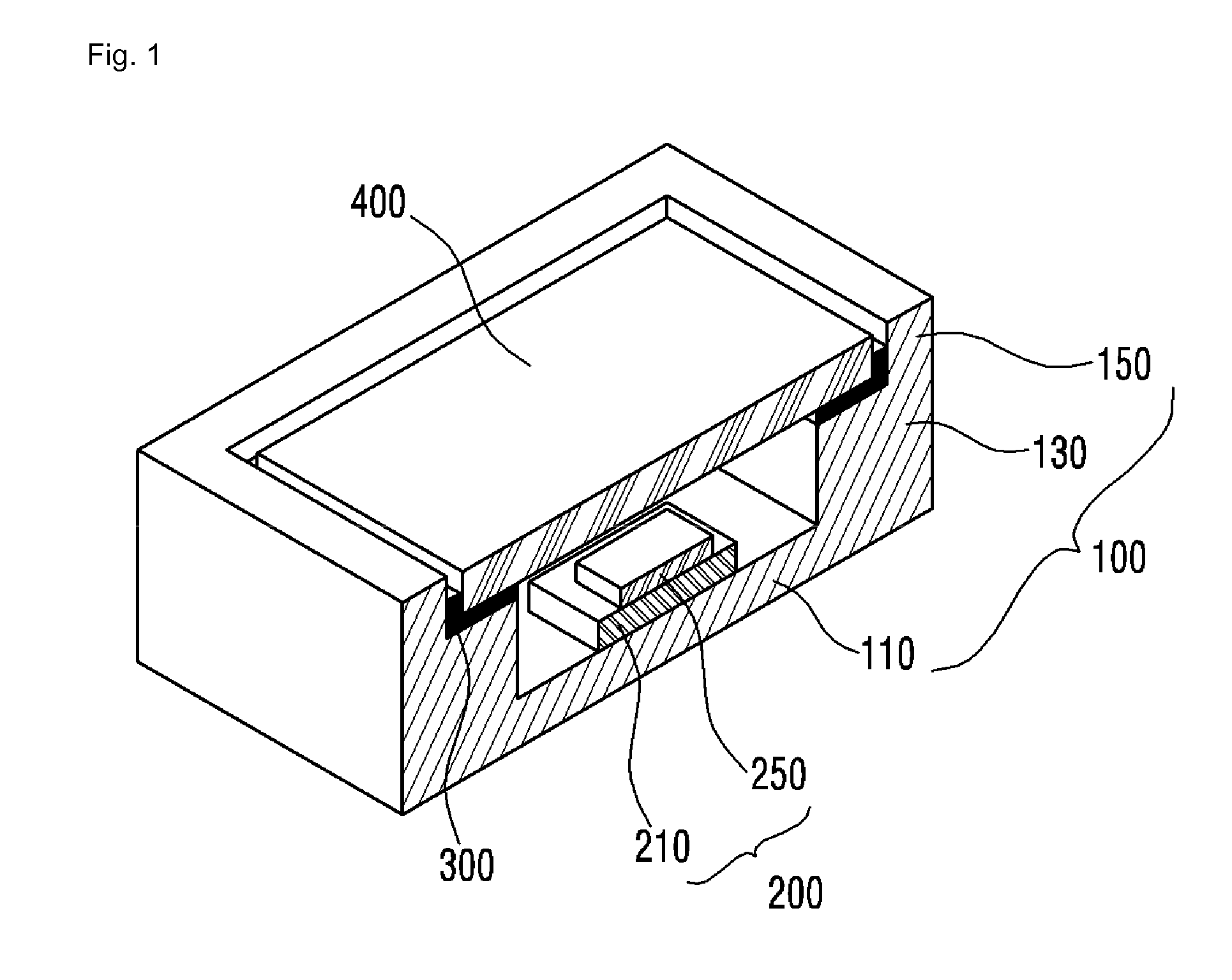
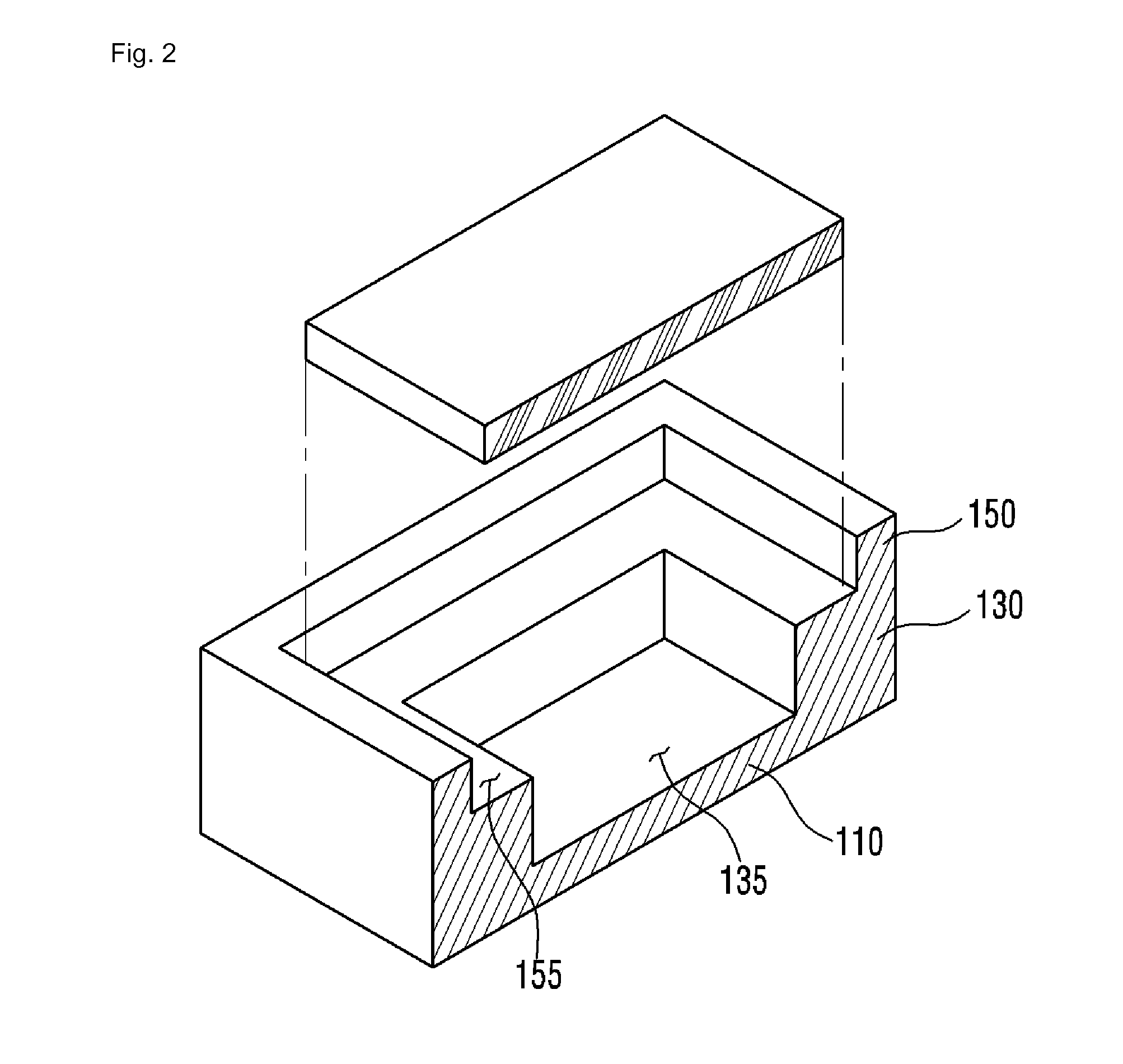
[0033]FIG. 1 is a cross-sectional perspective view of a light emitting module FIG. 2 is an exploded perspective view of the body and optical member of the light emitting module shown in FIG. 1, and FIG. 3 is a cross-sectional view of the light emitting module shown in FIG. 1.

[0034]Referring to FIGS. 1 to 3, the light emitting module according to the first embodiment may include a body 100, a light source unit 200, an adhesive member 300, and an optical member 400.

[0035]The light source unit 200, the adhesive member 300, and the optical member 400 are disposed in the body 100. Specifically, the light source unit 200, the adhesive member 300, and the optical member 400 are received in the body 100. In this case, the body 100 is coupled to the optical member 400 through the adhesive member 300. The body 100 is described in more detail.

[0036]The body 100 may include a lower portion 110, a wall portion 130, and an upper portion 150. In this case, the lower portion 110, the wall portion ...

second embodiment

[0065]FIG. 4 is a cross-sectional perspective view of a light emitting module FIG. 5 is an exploded perspective view of the body and optical member of the light emitting module shown in FIG. 4, and FIG. 6 is a cross-sectional view of the light emitting module shown in FIG. 4.

[0066]Referring to FIGS. 4 to 6, the light emitting module according to the second embodiment can prevent the discoloration or alteration of an adhesive member 300′ attributable to heat or UV rays emitted by the light emitting device 250.

[0067]The light emitting module according to the second embodiment includes a body 100′, a light source unit 200, the adhesive member 300′, and an optical member 400.

[0068]In describing the light emitting module according to the second embodiment shown in FIGS. 4 to 6 below, the same elements as those of the light emitting module according to the first embodiment shown in FIGS. 1 to 3 are assigned the same reference numerals. Accordingly, a detailed description of the elements ...

fifth embodiment

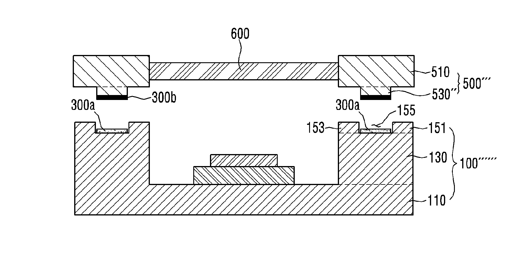
[0097]FIG. 9 is a cross-sectional perspective view of a light emitting module FIG. 10 is a perspective view showing that the body and cover of the light emitting module shown in FIG. 9 have been separated, and FIG. 11 is a cross-sectional view of the light emitting module shown in FIG. 9.

[0098]Referring to FIGS. 9 to 11, the light emitting module according to the fifth embodiment may include a body 100′″, a light source unit 200, a first adhesive member 300a, a second adhesive member 300b, a cover 500, and an optical member 600.

[0099]The light source unit 200, the first adhesive member 300a, the second adhesive member 300b, the cover 500, and the optical member 400 are disposed in the body 100′″. Specifically, the light source unit 200 is received in the body 100′″, the body 100′″ and the cover 500 are coupled through the first adhesive member 300a and the second adhesive member 300b, and the optical member 600 is coupled to the cover 500. The structure of the body 100′″ is describ...


PUM


Abstract

An embodiment relates to a light emitting module. A light emitting module according to an embodiment comprises: a light source unit comprising a light emitting device; a body comprising a lower portion on which the light source unit is arranged, a wall portion arranged on the lower portion and configured to surround the light source unit, and an upper portion arranged on the wall portion; an optical member arranged on the light source unit to transmit light from the light emitting device; and an adhesive member arranged between the wall portion of the body and the optical member to couple the body and the optical member, wherein the upper portion of the body is arranged between the light emitting device and the adhesive member.

Description

TECHNICAL FIELD[0001]An embodiment relates to a light emitting module.BACKGROUND ART[0002]III group nitrides, such as gallium nitride (GaN), aluminum nitride (AlN), and indium gallium nitride (InGaN), are chiefly used in a light-emitting diode (LED) because they have excellent thermal stability and a directly shift energy band structure. Specifically, the III group nitrides are chiefly used in a blue LED and an ultraviolet LED (UV LED).[0003]An UV LED which emits UV rays is packed in a specific body (or case), fabricated, and sold. In this case, the UV rays emitted by the UV LED may discolor or alter other parts including the body of a light emitting module. The discoloration or alteration of the body or other parts attributable to UV rays may have a bad effect on reliability or durability of a light emitting module including an UV LED.DISCLOSURETechnical Problem[0004]A light emitting module according to an embodiment can prevent an adhesive member from being discolored or altered d...

Claims


Application Information

Patent Timeline
Patent Type & Authority Applications(United States)
IPC IPC(8): H01L33/48H01L33/50
CPCH01L33/502H01L33/486H01L33/58H01L2924/16195H01L2924/16315
Inventor KIM, HA NAKIM, BYUNG MOK
Owner SUZHOU LEKIN SEMICON CO LTD
Why Eureka
Try Eureka