Surge protective system

a surge protection and system technology, applied in the field of surge protection systems, can solve the problems of inability to make the surge protection system of the related art more compact, difficult to store the surge protection system in a small distribution frame or a small spd frame, etc., and achieve the effect of compact surge protection system

Active Publication Date: 2016-05-05
SANKOSHA CORP
View PDF6 Cites 8 Cited by
  • Summary
  • Abstract
  • Description
  • Claims
  • Application Information

AI Technical Summary

Benefits of technology

[0009]Therefore, to solve the above-described problems of the related art, an object of the present invention is to provide a surge protective system which can be sto

Problems solved by technology

However, there are the following problems (1) and (2) in the surge protective system of the related art.
Therefore, when space to store a distribution frame or an SPD frame is small, it is difficult to store the surge protective system of the related art because i

Method used


Image

  • Surge protective system
  • Surge protective system
  • Surge protective system

Examples


first embodiment

Configuration of the First Embodiment

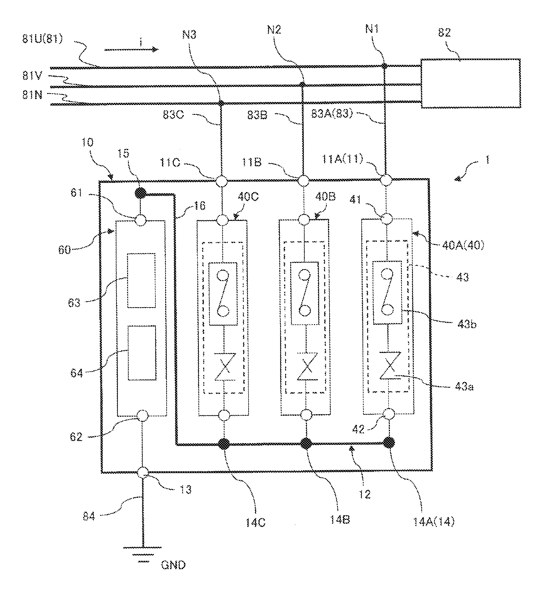
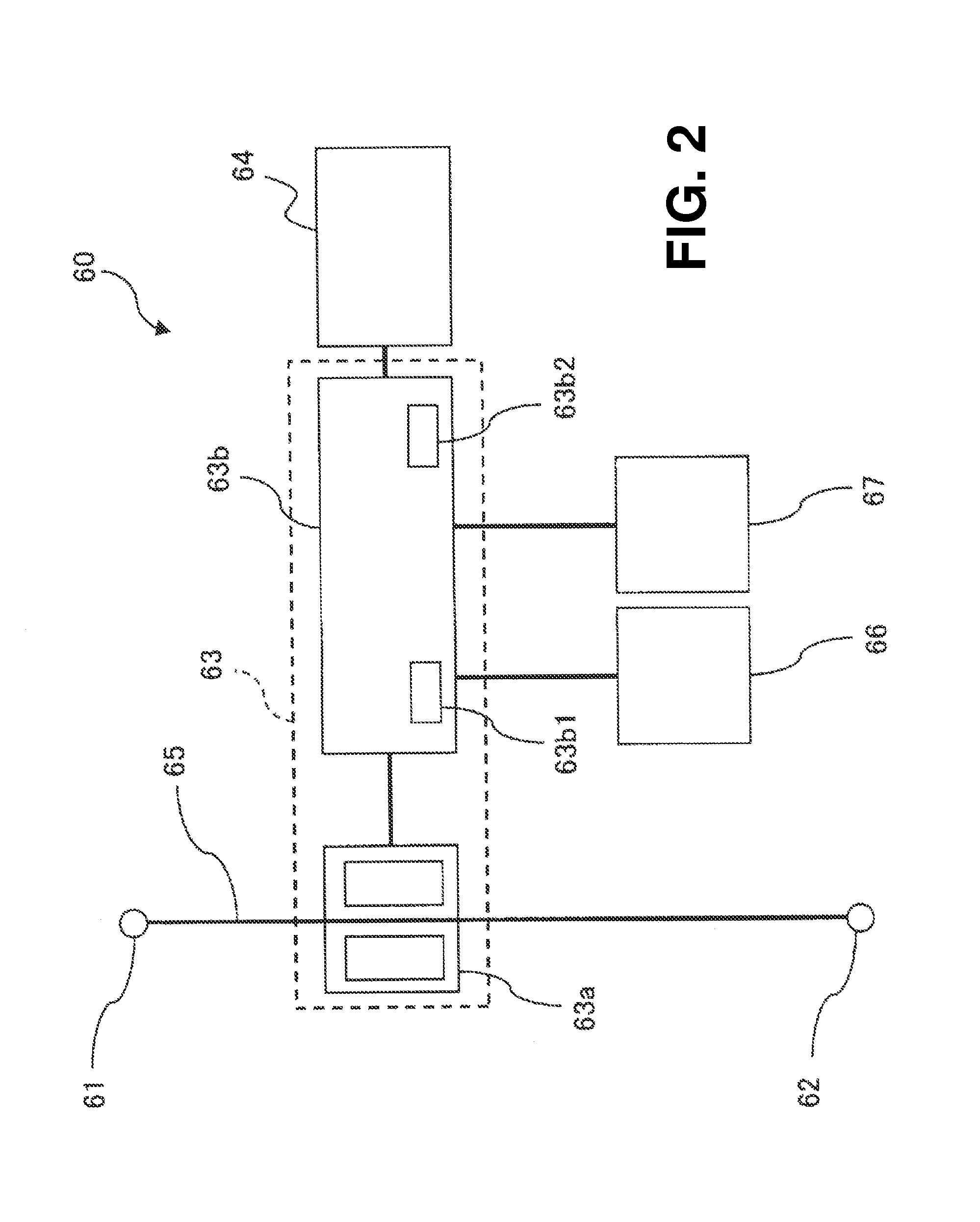
[0036]FIG. 1 is a schematic circuit configuration diagram illustrating the whole of a surge protective system 1 according to the first embodiment of the present invention. The surge protective system 1 is a system for protecting equipment to be protected 82 connected to a plurality of lines 81 of a power wire against a lightning surge current i. The plurality of lines 81 are, for example, single-phase three-wire power wires for supplying an input voltage (AC200V) having a ground phase. The plurality of lines 81 include, for example, three lines 81U, 81V and 81N. The surge protective system 1 is connected to a plurality of line side wires 83 which is branched from the three lines 81 at branch points N1, N2 and N3. The plurality of line side wires 83 include, for example, three line side wires 83A, 83B and 83C.

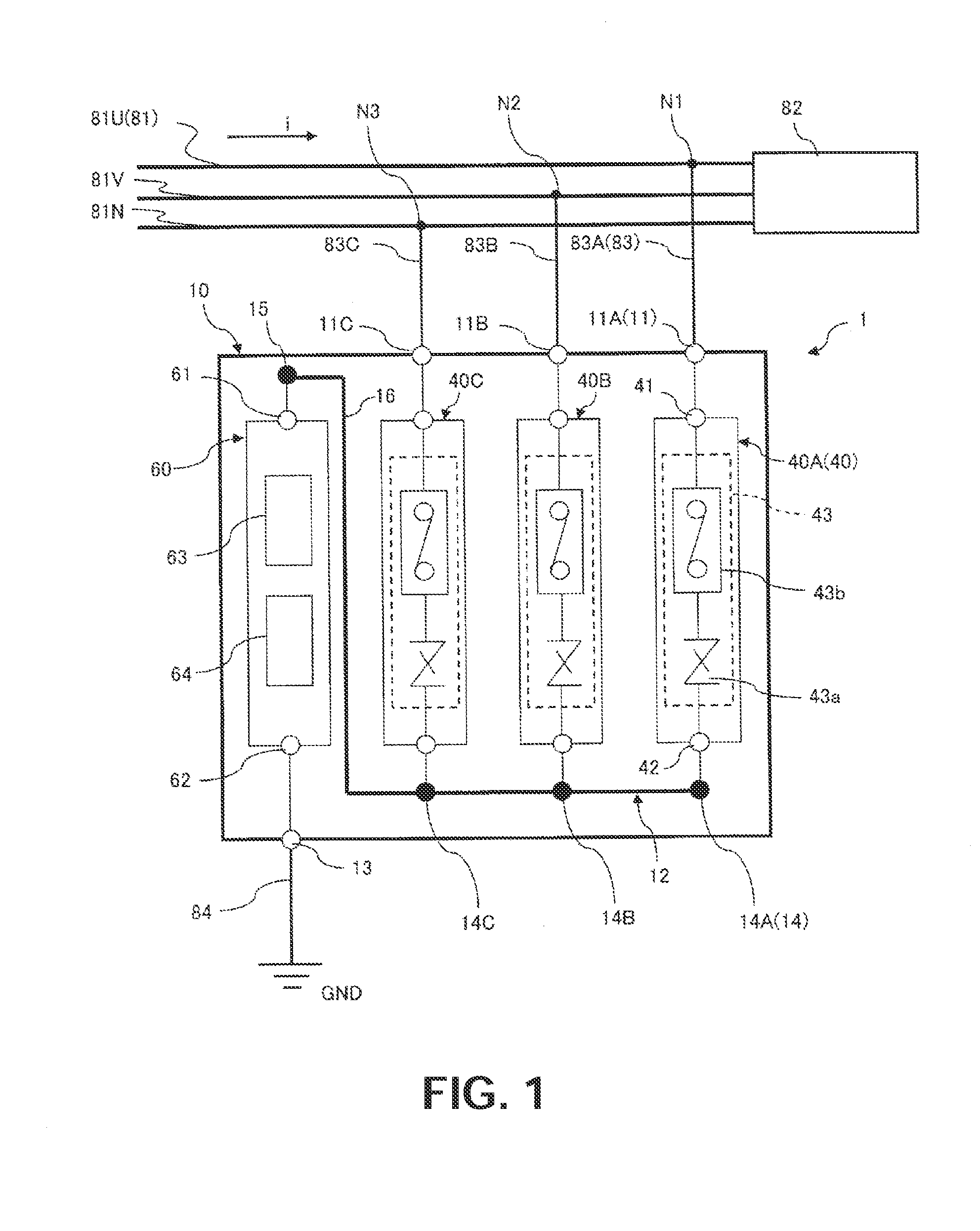
[0037]The surge protective system 1 is configured with a plinth 10 for wiring, a plurality of SPDs 40 and one surge detector 60. The plinth ...

second embodiment

Configuration of the Second Embodiment

[0085]FIG. 19 is a schematic circuit configuration diagram illustrating the whole of a surge protective system 1B according to the second embodiment of the present invention, in which the same reference numerals are assigned to the same components as the components in FIG. 1 which illustrates the first embodiment.

[0086]The surge protective system 1B has a surge detector 60B which is different from the surge detector 60 in FIG. 1 in place of the surge detector 60 in FIG. 1. The surge detector 60B is different from the surge detector 60 in that an arrester 79 as a lightning device is connected between the 3rd contact 61 and the 4th contact 62. The arrester 79 is a lightning tube which discharges an input lightning surge current i. The other components of the surge protective system 1B are the same as the components of the surge protective system 1 in the first embodiment.

Operation of the Surge Protective System of the Second Embodiment

[0087]Operat...


PUM


Abstract

A surge protective system has a plinth for wiring and is connected between a plurality of line side wires and a ground wire. A plurality of surge protective devices (SPDs) and one surge detector are disposed in parallel and detachably fitted into and attached to the plinth. The plinth has a wiring metal fitting for connecting the plurality of SPDs and the one surge detector. When a lightning surge current enters into the surge protective system from the line side wires, the lightning surge current flows to the surge detector through the SPDs, a 1st plinth contact part in the wiring metal fitting, a connection part and a 2nd plinth contact part. The lightning surge current flowing to the surge detector is discharged to the ground through the ground wire.

Description

BACKGROUND ART[0001]1. Field of the Invention[0002]The present invention relates to a surge protective system for protecting equipment to be protected against a lightning surge current flowing to a ground wire from a line of a power wire or a communication wire.[0003]2. Description of the Related Art[0004]As disclosed in, for example, Japanese Patent Laid-Open No. 2013-077483, a surge protective system of the related art protects equipment to be protected against a lightning surge current flowing to a ground wire from a line of a power wire or a communication wire. The surge protective system has a surge protective device (hereinafter, referred to as an “SPD”) for discharging a lightning surge current to the ground wire. The SPD is detachably fitted into and attached to a plinth for wiring. A surge detector for detecting a lightning surge current and performing display is detachably attached at a side of the ground wire of the plinth.[0005]The line of the power wire or the communica...

Claims


Application Information

Patent Timeline
IPC IPC(8): H02H9/04
CPCH02H9/04H01C7/10H01C7/12
Inventor KAWABATA, TSUYOSHI
Owner SANKOSHA CORP
Why Eureka
Try Eureka