
Polyaxial bone plate and locking assembly

a technology which is applied in the field of polyaxial bone plate and locking assembly, can solve the problems of significantly affecting the mobility and activity of patients, the impracticality of external immobilization, and the inability to fully engage the spine, and achieves the effect of simple us

Active Publication Date: 2016-05-12
MEDITECH SPINE
View PDF4 Cites 15 Cited by
  • Summary
  • Abstract
  • Description
  • Claims
  • Application Information

AI Technical Summary

Benefits of technology

The patent describes better bone plates and locking assemblies for spinal surgery. These plates and locks are designed to be easy to install, with minimal parts that could be lost during surgery. The locking mechanism is simple and secure, and does not require any specialized equipment. The technical effects are improved bone plates and locking assemblies that are both secure and easy to use.

Problems solved by technology

When a break or fracture is in the spine, or when the connective tissue between one or more vertebrae is damaged, external immobilization is significantly less effective for several reasons.
Because the spine is the central support column of the human body, externally imposed immobilization is impractical, as it involves immobilizing most of the body.
Furthermore, the spine is a load-bearing structure that is subject to repetitive compressive and rotational stresses constantly during the normal waking life of a person; therefore, external immobilization of the spine significantly impacts the mobility and activity of a patient.
In practice, the fact that such devices must be attached in surgery restricts the amount of time and the amount of access to the bone, such that physicians require such devices to attach efficiently and primarily from one direction.
Another significant challenge to the use of bone plates is the stress placed on the bone by the tightening of the bone screws.
However, the force generated by tightening screws to achieve such friction in bone may cause excessive damage, and the healing of the bone over time in combination with the motion of the body may act to gradually force the bone screw from its position.
Anti-backout mechanisms on bone plates tend to suffer a variety of drawbacks.
Parts of conventional anti-backout mechanisms, for instance screws and washers, tend to be small and delicate, and can be broken during installation or lost by the surgeon within the surgical wound.
In conventional bone plates that possess internal anti-backout mechanisms, securing the mechanism may require specialized tools, or it may be difficult to ascertain whether the anti-backout mechanism has been fully engaged.

Method used


Image

  • Polyaxial bone plate and locking assembly
  • Polyaxial bone plate and locking assembly
  • Polyaxial bone plate and locking assembly

Examples


Embodiment Construction

[0031]The subject matter of embodiments of the present invention is described here with specificity to meet statutory requirements, but this description is not necessarily intended to limit the scope of the claims. The claimed subject matter may be embodied in other ways, may include different elements or steps, and may be used in conjunction with other existing or future technologies. This description should not be interpreted as implying any particular order or arrangement among or between various steps or elements except when the order of individual steps or arrangement of elements is explicitly described.

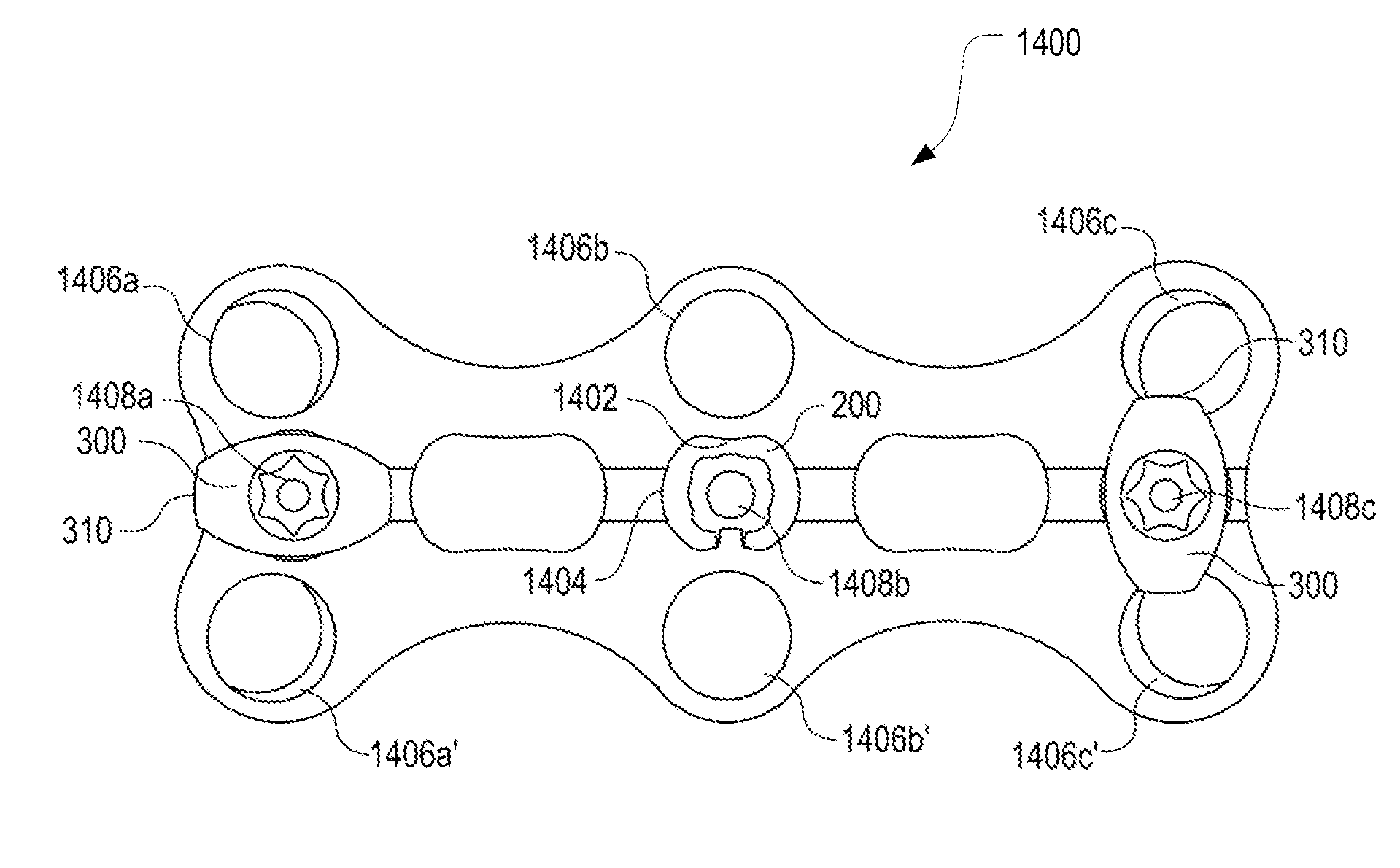
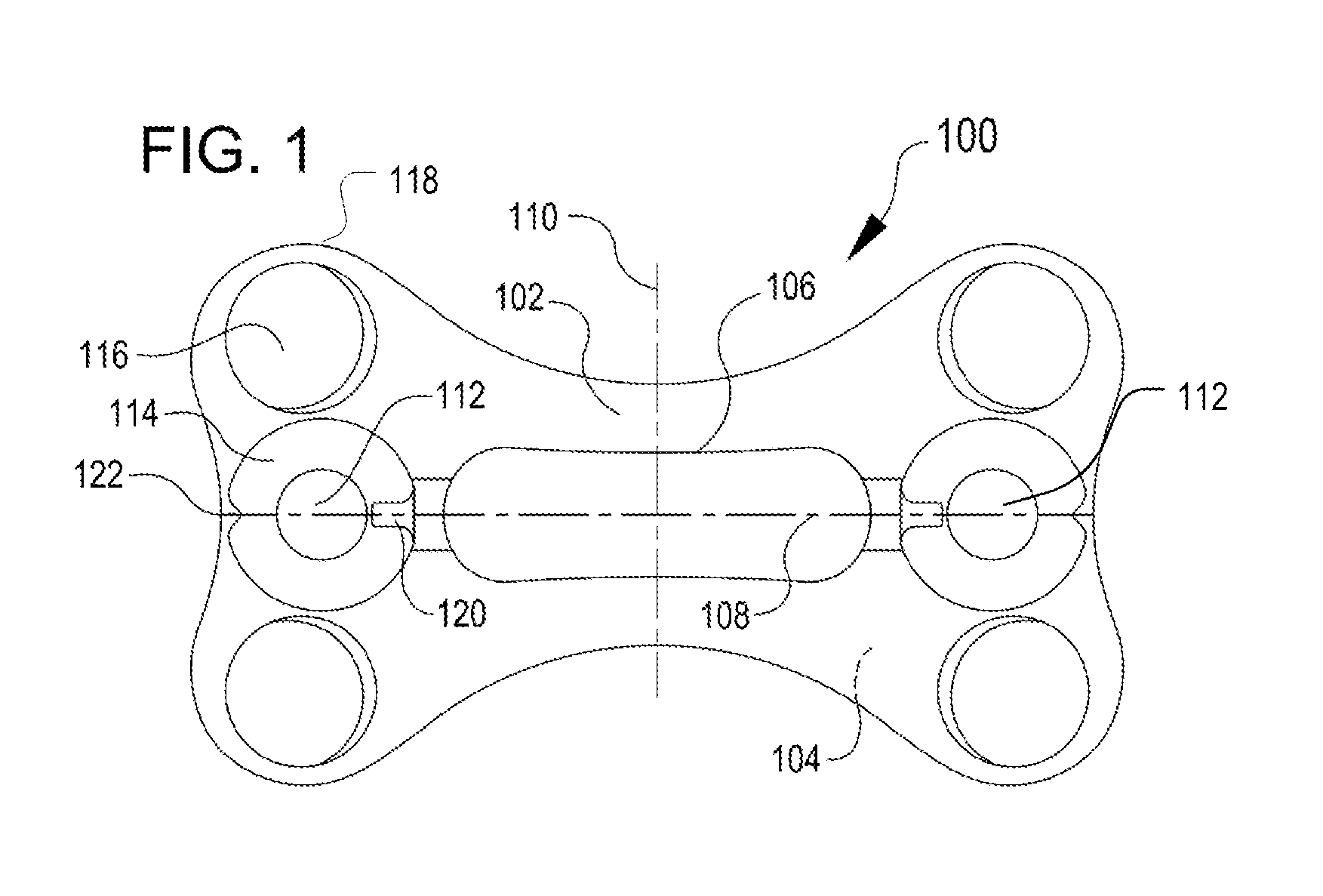
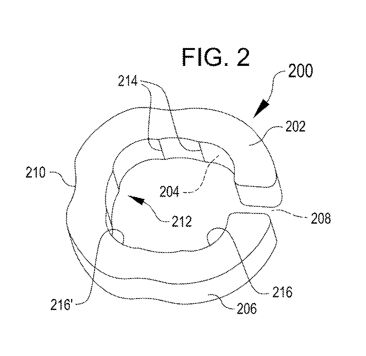
[0032]This patent discloses polyaxial bone plates and locking mechanisms that are configured for immobilization of vertebral bodies via fixation to surfaces thereof, with features for preventing screw backout while minimizing certain risks and the time required for surgical installation.

[0033]As shown in the Figures, a bone plate includes a plurality of through-holes for receivi...


PUM


Abstract

A cervical plate and one or more locking assemblies that help prevent screw backout without impinging on therapeutically valuable settling of the screws. In some cases, the locking assembly is configured to be permanently attached to the plate, to be securely but efficiently locked, to be readily unlocked for revision surgery, and / or to reduce the possibility of operator error in installation by providing simplified visible and tactile indicia of the locked and unlocked positions.

Description

CROSS-REFERENCES TO RELATED APPLICATION[0001]This application claims the benefit of U.S. Provisional Application No. 62 / 077,508 for “Polyaxial Bone Plate and Locking Assembly” filed Nov. 10, 2014, which is incorporated in this application in its entirety by this reference.FIELD OF INVENTION[0002]This application relates to implantable internal fixator assemblies for use in stabilizing and supporting the spine.BACKGROUND OF THE INVENTION[0003]Broken bones heal naturally, albeit slowly compared to most soft tissue, provided they are adequately supported and relieved of stress. In a simple break in an extremity, adequate support and relief may be provided from outside the body with a device as simple as a splint or a cast, which immobilizes the body part containing the broken bone. Such procedures may suffice when the bone can be set and will retain its position without significant intervention, for instance when the break is simple and contained in a body part that can be readily immo...

Claims


Application Information

Patent Timeline
IPC IPC(8): A61B17/80A61B17/70
CPCA61B17/7059A61B17/8042A61B17/80A61B17/8033
Inventor DUNAWAY, ROBERT BRUCE
Owner MEDITECH SPINE
Learn More