Reverberation chamber with improved electromagnetic field uniformity

a reverberation chamber and electromagnetic field technology, applied in the field of reverberation chambers, can solve the problems of arbitrary generator use and limited speed of electromagnetic field, and achieve the effect of improving electromagnetic field uniformity and reducing the lowest usable frequency of reverberation chambers

Inactive Publication Date: 2016-05-12
CENT NAT DE LA RECHERCHE SCI +2
View PDF10 Cites 10 Cited by
  • Summary
  • Abstract
  • Description
  • Claims
  • Application Information

AI Technical Summary

Benefits of technology

[0008]The present invention seeks to remedy the above-mentioned drawbacks and to improve the uniformity of the electromagnetic f

Problems solved by technology

Nevertheless, its speed is limited in order to ensure that conditions are steady.
This requires additional antennas

Method used


Image

  • Reverberation chamber with improved electromagnetic field uniformity
  • Reverberation chamber with improved electromagnetic field uniformity
  • Reverberation chamber with improved electromagnetic field uniformity

Examples


Embodiment Construction

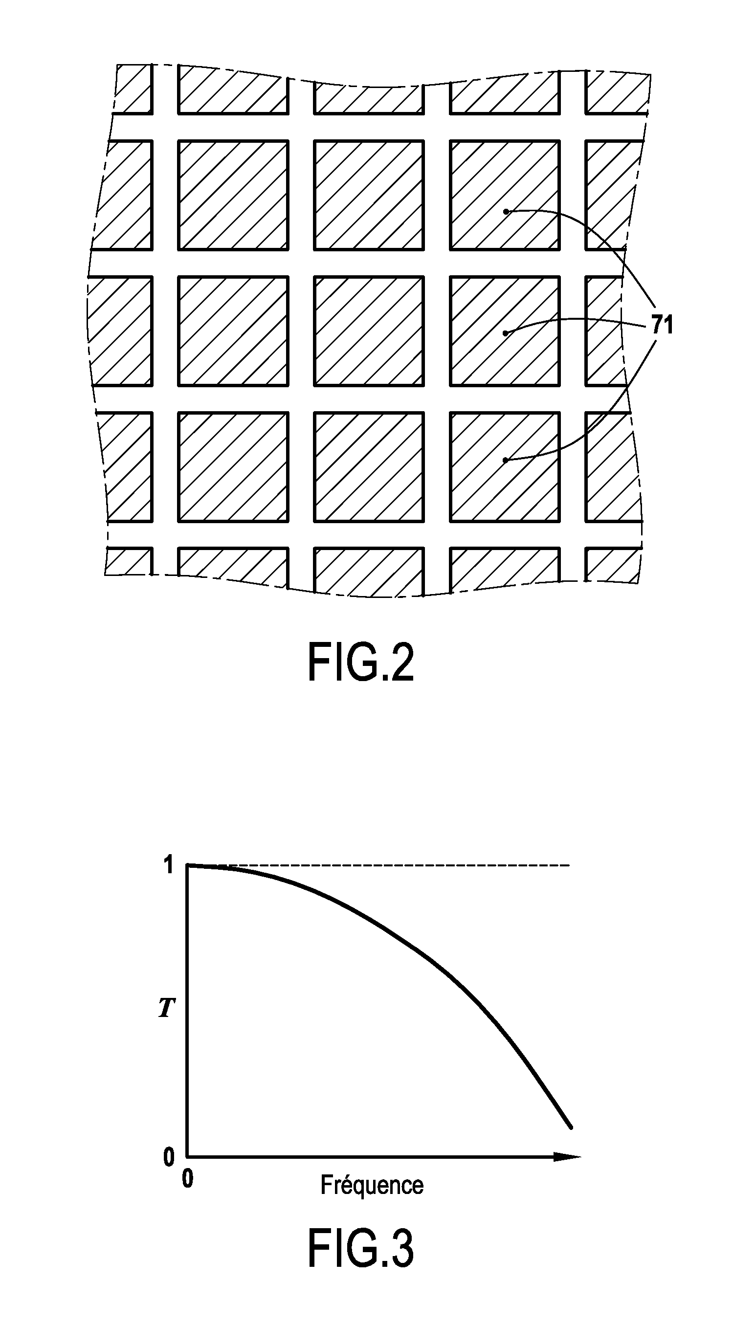
[0038]The technique proposed in the invention serves to obtain local improvement in the uniformity of the EM field with an optional and preferred possibility of lowering the LUF.

[0039]This technique presents two major advantages over the above-summarized techniques of the prior art. The first advantage is that it is purely passive, i.e. it does not require any additional generator other than the generator that is conventionally used in a reverberation chamber. The second advantage is that constitutes an item that is transportable without any constraint specific to placement within the reverberation chamber.

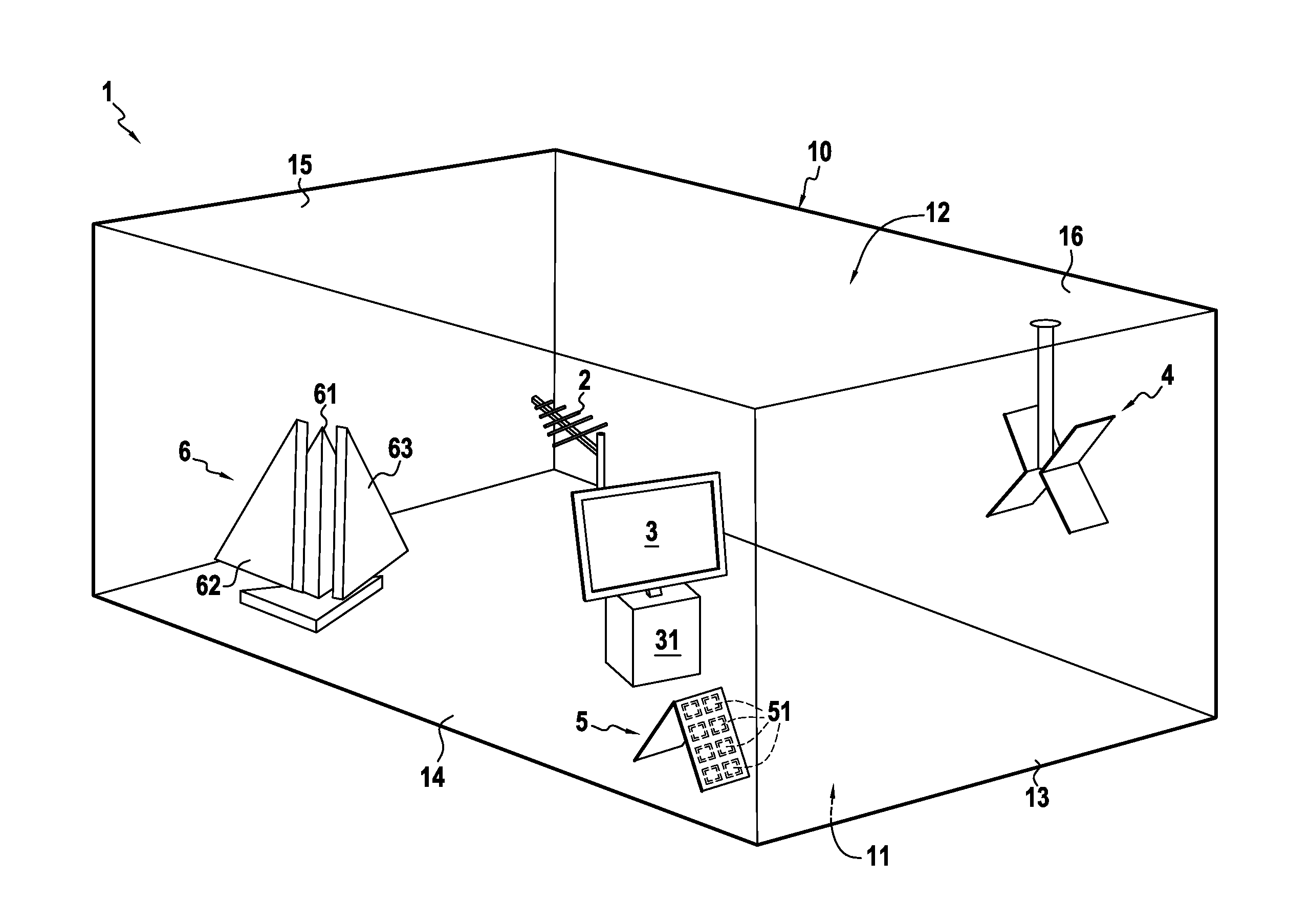
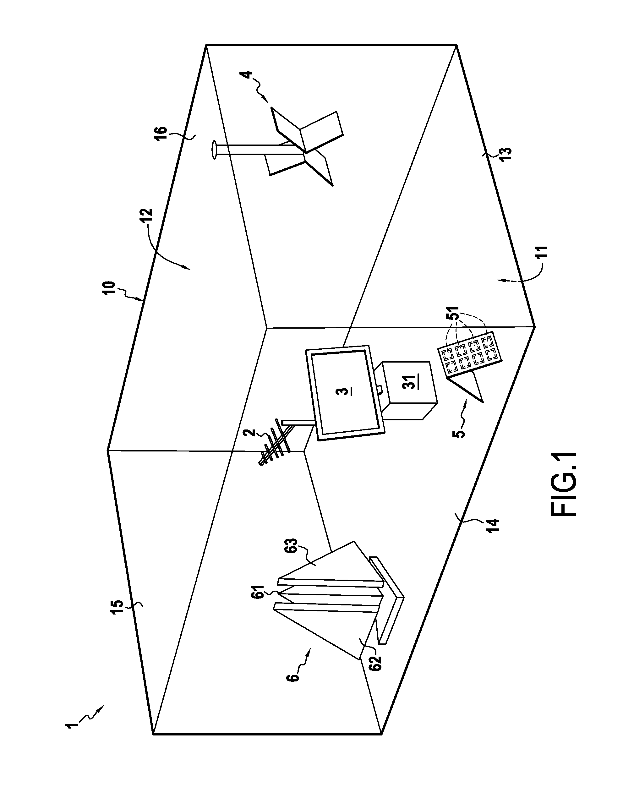
[0040]FIG. 1 shows an example of placing frequency-selective absorbers in a mode-stirring reverberation chamber 1 that comprises a shielded enclosure 10 having a floor 11, side walls 13 to 16, and a ceiling 12.

[0041]An article under test 3 is shown inside the reverberation chamber, which article may for example be a TV set or any other type of electrical or electronic apparatus th...


PUM


Abstract

The reverberation chamber comprises a shielded enclosure (10) made up of a floor (11), side walls (13 to 16), and a ceiling (12), together with an antenna (2) for emitting radiofrequency waves in order to generate radiation inside the enclosure (10) at a lowest usable frequency. The chamber also comprises, inside the enclosure (10), a set (5, 6) of passive and selective elements for absorbing radiofrequencies in a defined frequency band.

Description

FIELD OF THE INVENTION[0001]The present invention relates to a reverberation chamber having a shielded enclosure constituted by a floor, side walls, and a ceiling, together with a radiofrequency wave emitter antenna for generating radiation inside the enclosure at a lowest usable frequency.PRIOR ART[0002]Reverberation chambers with mode stirring are electromagnetic compatibility test means that comprise a shielded enclosure forming a Faraday cage inside which an apparatus for testing is inserted. Use is made of the resonant modes of the cavity as defined by the enclosure.[0003]A reverberation chamber thus makes it possible, among other things, to test electrical equipment in order to discover the influence that surrounding electromagnetic radiation can have on the electrical equipment, or vice versa, in order to determine the electromagnetic energy that is emitted by the electrical equipment into its environment.[0004]Nowadays mode stirring is thus performed essentially in the micro...

Claims


Application Information

Patent Timeline
IPC IPC(8): G01R29/08
CPCG01R29/0821
Inventor MONSEF, FLORIAN
Owner CENT NAT DE LA RECHERCHE SCI
Why Eureka
Try Eureka