Susceptor design to reduce edge thermal peak

a technology of susceptor and edge, applied in the field of susceptor, can solve the problems of temperature non-uniformity across the substrate and reduce the quality of the layers deposited on the substra

Active Publication Date: 2016-05-12
APPLIED MATERIALS INC
View PDF5 Cites 185 Cited by
  • Summary
  • Abstract
  • Description
  • Claims
  • Application Information

AI Technical Summary

Problems solved by technology

Despite the precise control of heating the susceptor, it has been observed that the susceptor may cause temperature non-uniformity across the substrate due to non-uniform heat convection or conduction heat losses from regions of the substrate in contact with the susceptor and substrate regions not in contact with the susceptor.
Temperature non-uniformities persist across the upper surface of the substrate often reducing the quality of the layers deposited on the substrate.

Method used


Image

  • Susceptor design to reduce edge thermal peak
  • Susceptor design to reduce edge thermal peak
  • Susceptor design to reduce edge thermal peak

Examples


Embodiment Construction

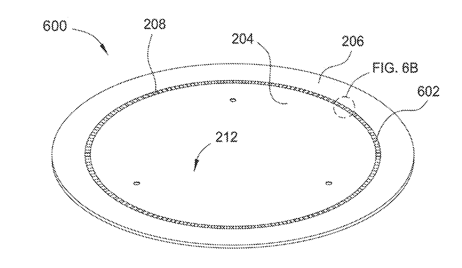
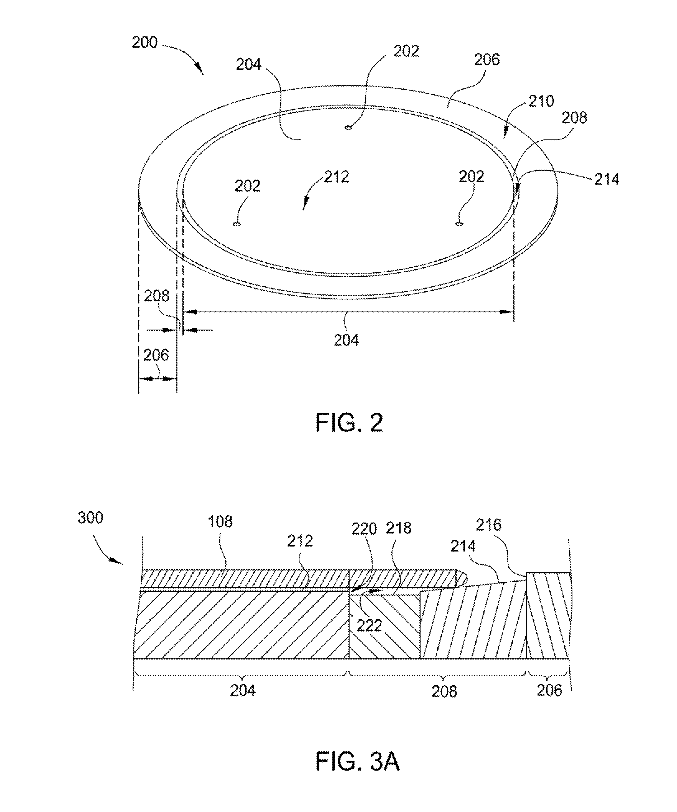
[0028]Implementations of the present disclosure generally relate to a susceptor for thermal processing of semiconductor substrates. Implementations disclosed can improve thermal uniformity across the surface of a substrate during processing by reducing a contacting surface area between the susceptor and the substrate. Reducing the contacting surface area between the susceptor and the substrate reduces the amount of heat that is transferred from the susceptor to the substrate by conduction during processing. In some Implementations, the angled surface of the susceptor that is in contact with the substrate may have a plurality of cut-outs or tabs to provide azimuthal heat uniformity around the circumference of the susceptor. In some Implementations, the susceptor may further provide a plurality of radial channels around the circumference of the susceptor to help venting of the heat or gas flow during processing. Details of the Implementations of the susceptor are described below.

Exemp...


PUM

PropertyMeasurementUnit
angleaaaaaaaaaa
pressureaaaaaaaaaa
pressureaaaaaaaaaa

Abstract

Implementations of the present disclosure generally relate to a susceptor for thermal processing of semiconductor substrates. In one implementation, the susceptor includes a first rim surrounding and coupled to an inner region, and a second rim disposed between the inner rim and the first rim. The second rim includes an angled support surface having a plurality of cut-outs formed therein, and the angled support surface is inclined with respect to a top surface of the inner region.

Description

CROSS-REFERENCE TO RELATED APPLICATIONS[0001]This application claims benefit of U.S. provisional patent application Ser. Nos. 62 / 078,782, filed Nov. 12, 2014 and 62 / 084,821, filed Nov. 26, 2014, which are herein incorporated by reference.BACKGROUND[0002]1. Field[0003]Implementations of the present disclosure generally relate to a susceptor for use in a thermal process chamber.[0004]2. Description of the Related Art[0005]Semiconductor substrates are processed for a wide variety of applications, including the fabrication of integrated devices and microdevices. During processing, the substrate is positioned on a susceptor within a process chamber. Susceptors often have platter or dish-shaped upper surfaces that are used to support the substrate from below around the edges of the substrate while leaving a small gap between the remaining lower surface of the substrate and the upper surface of the susceptor. The susceptor is supported by a support shaft, which is rotatable about a central...

Claims


Application Information

Patent Timeline
Patent Type & Authority Applications(United States)
IPC IPC(8): H01L21/687H01L21/67
CPCH01L21/68785H01L21/67098H01L21/68735H01L21/67115H01L2221/683C23C16/4583H01L21/6835
Inventor CHU, SCHUBERT S.SHAH, KARTIKNGO, ANHTHURAMANATHAN, KARTHIKPATHAK, NITINMYO, NYI O.BRILLHART, PAULCOLLINS, RICHARD O.BAUTISTA, KEVIN JOSEPHTONG, EDRICCONG, ZHEPENGCHANG, ANZHONGLO, KIN PONGHEMKAR, MANISH
Owner APPLIED MATERIALS INC
Why Eureka
Try Eureka