Supercharge Your Innovation With Domain-Expert AI Agents!

Engine control apparatus

a technology of control apparatus and engine, which is applied in the direction of electrical control, fuel supply apparatus, thermal treatment of fuel, etc., can solve the problems of limited space under the hood of modern engines, increased burden of software development, and difficult packaging and mounting

Inactive Publication Date: 2016-05-19
WESTPORT POWER
View PDF7 Cites 2 Cited by
  • Summary
  • Abstract
  • Description
  • Claims
  • Application Information

AI Technical Summary

Benefits of technology

The patent describes an improved engine control system for gaseous fuel engines. The system includes a control unit that monitors and controls the fuel system, including the fuel pump and fuel injection apparatus. The control unit also monitors the engine's operating conditions and can actuate a positive ignition source. The system also includes a liquefied gaseous fuel storage vessel and a gaseous fuel pumping apparatus to introduce gaseous fuel into the combustion chamber. The control unit can also monitor the quantity of liquefied gaseous fuel remaining in the storage vessel and control the pumping apparatus to maintain the desired pressure. The system allows for precise control of gaseous fuel pressure and quantity, and can also introduce liquid fuel into the combustion chamber as needed.

Problems solved by technology

However, separate control units create a packaging and mounting challenge for vehicle system integrators where space under the hood in modern engines is limited.
Power and communication harnesses need to be routed to the additional control units presenting other potential points of failure in the engine electrical system.
There is an increased burden when developing software for each control unit that must intercommunicate with other control units.
In modern high speed engines there can be time constraints that make inter-control unit communication a potential bottle neck for receiving and / or responding to engine events due to the limited bandwidth between the control units thereby limiting the control bandwidth of the engine and possibly the maximum engine speed.
The complexity of software maintenance and deployment is increased in a multi-control unit environment.
The state of the art is lacking in techniques for integrating additional control modules in the existing engine control apparatus in engines that have been converted or adapted to be fuelled with an alternative fuel, such as a gaseous fuel.

Method used


Image

  • Engine control apparatus
  • Engine control apparatus
  • Engine control apparatus

Examples


Embodiment Construction

)

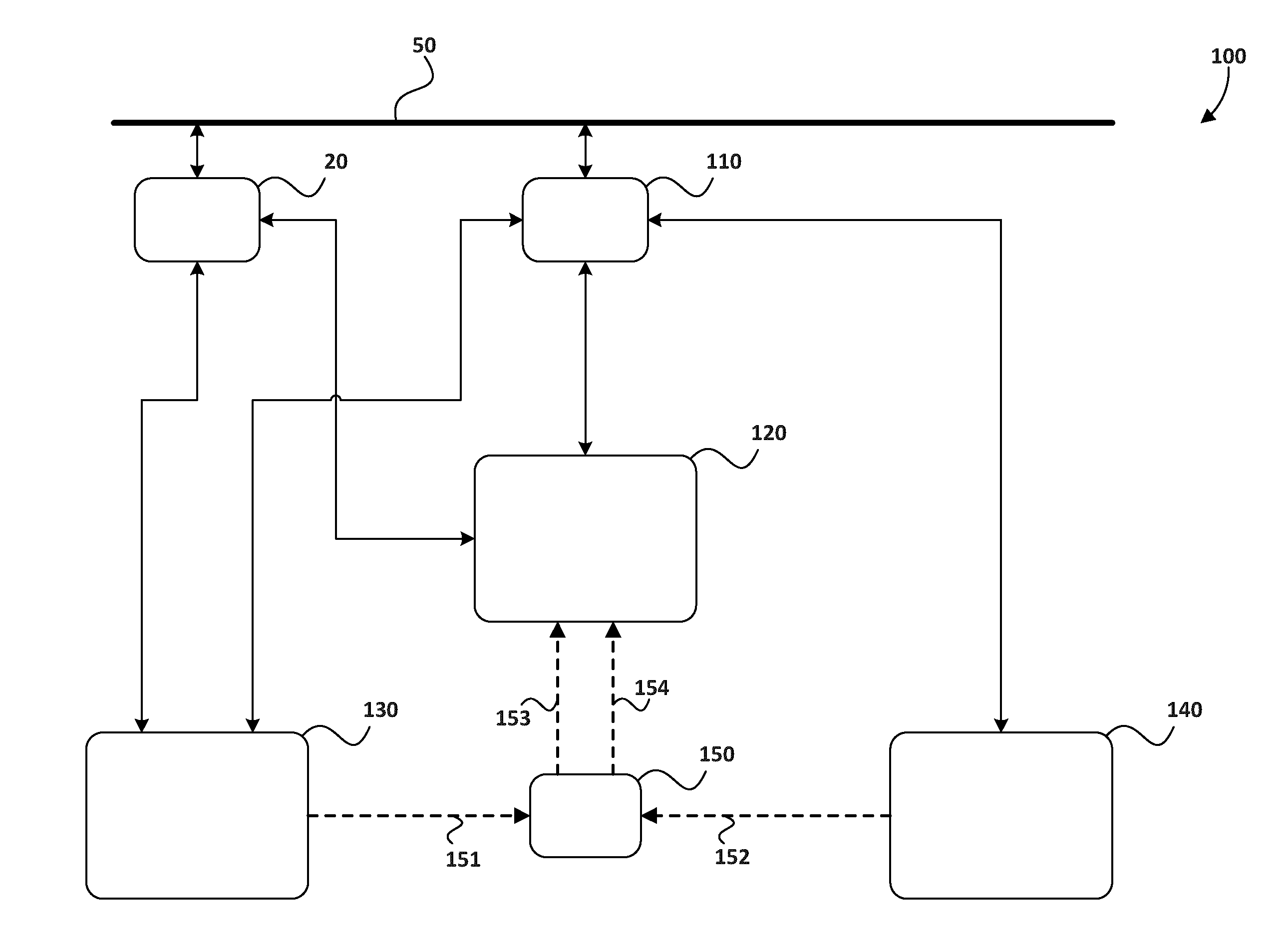
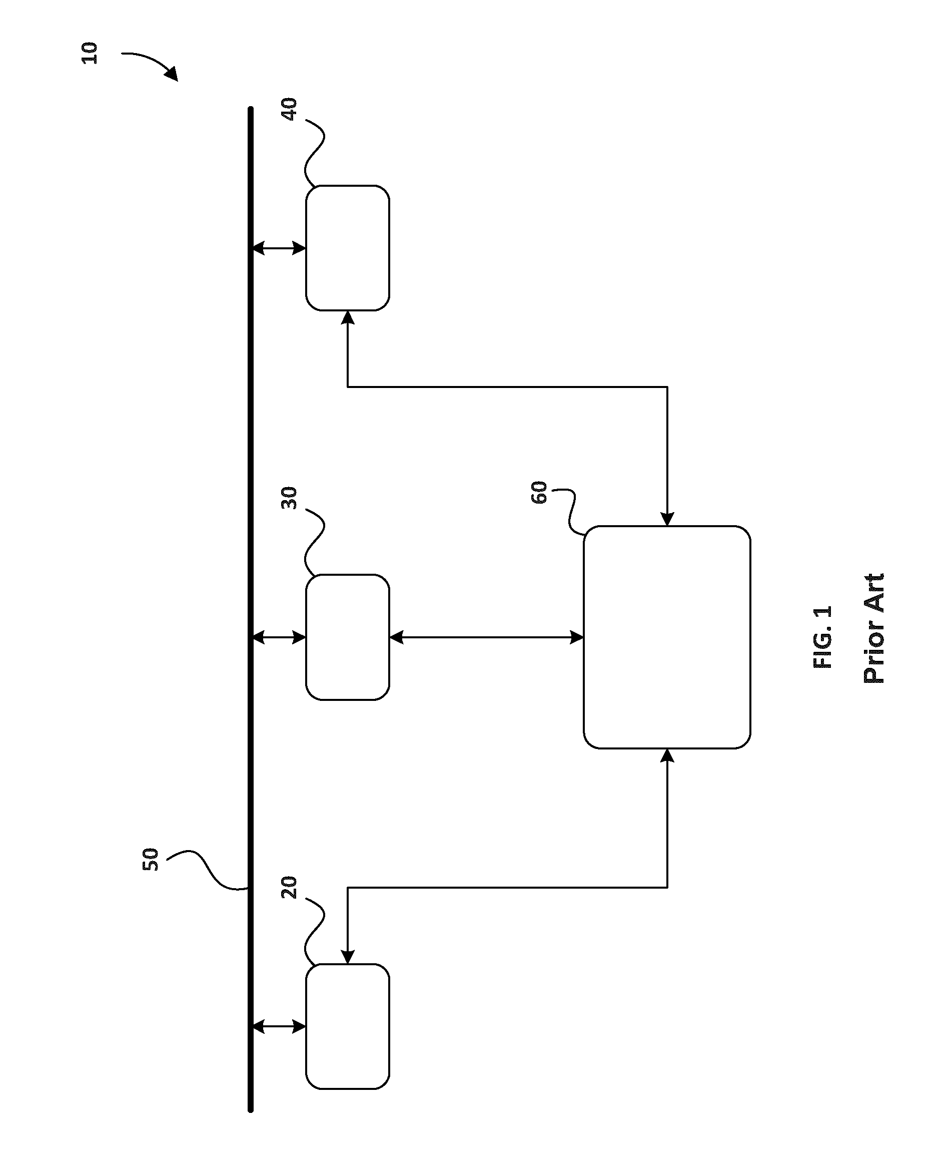
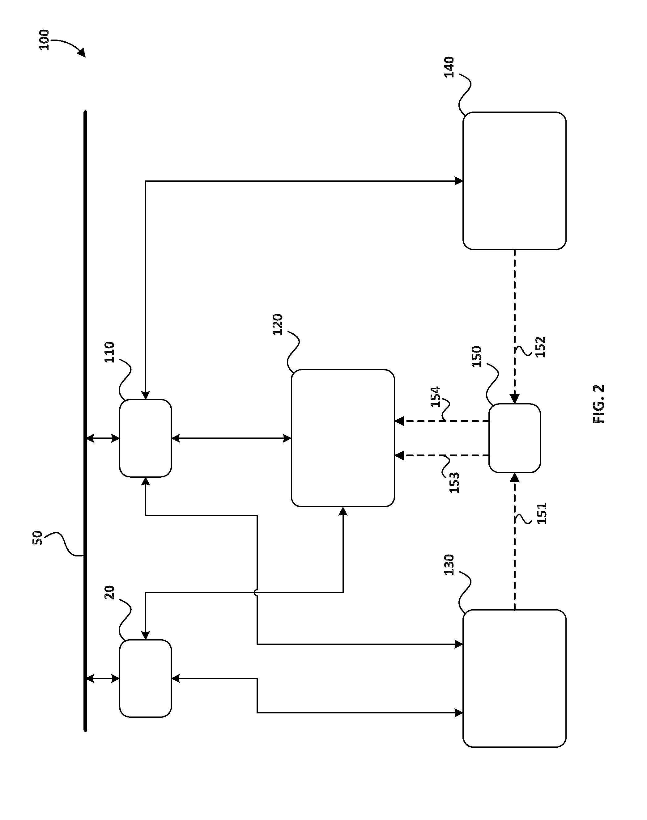
[0022]In the description of the subject engine control apparatus a number of different embodiments are described, and in the figures like parts and components are indicated by like reference numerals and if essentially in the same form and function such parts and components already described may not be described in detail, if at all. In all the figures herein, dashed lines represent piping for fluid flow and the arrows on the dashed lines represents the direction of flow, solid lines with a single arrow represent unidirectional electrical communications, and solid lines with an arrow at each end represent bi-directional communication. The solid lines can represent a single wire or a grouping of wires.

[0023]With reference to FIG. 2, engine system 100 comprises base engine control unit 20 and fuel system and liquefied gaseous fuel control unit 110, which communicate with each other over bus 50. Internal combustion engine apparatus 120 is fuelled with both a liquid fuel and a gaseous ...


PUM


Abstract

Engines fuelled with gaseous fuel stored in liquefied form comprise different strategies and controls for managing gaseous fuel compared to other systems, previously resulting in an ad hoc arrangements of controllers. An engine control apparatus comprises an internal combustion engine fuelled with a gaseous fuel stored in liquefied form and a control unit programmed with a fuel system module, for monitoring gaseous fuel pressure and actuating a fuel injection apparatus for introducing gaseous fuel into a combustion chamber, and a liquefied gaseous fuel module, for monitoring the quantity of liquefied gaseous fuel remaining in a storage vessel and controlling a pumping apparatus that pumps liquefied gaseous fuel from the storage vessel to a vaporizer. The fuel system control module and the liquefied gaseous fuel control module cooperate to introduce gaseous fuel in the combustion chamber at a predetermined pressure as a function of engine operating conditions.

Description

FIELD OF THE INVENTION[0001]The present application relates to an engine control apparatus for controlling an internal combustion engine fuelled with a gaseous fuel, and more particularly with a gaseous fuel stored in liquefied form.BACKGROUND OF THE INVENTION[0002]Modern automobiles and trucks typically employ several control units to manage the various components associated with an internal combustion engine and the vehicle in general. Typically, there is a base engine control unit for managing the internal combustion engine and a number of additional control units distributed throughout the vehicle for managing off engine components. The trend in modern automobile control design is to employ multiple distributed dedicated controllers that manage specific functions and tasks, and which communicate with the base engine control unit. The base engine control unit is a type of electronic control unit that controls a series of actuators on the engine to ensure the engine is operating w...

Claims


Application Information

Patent Timeline
IPC IPC(8): F02D41/30F02B1/02F02M31/18F02D19/02F02M21/06F02M21/02
CPCF02D41/3005F02M21/06F02M21/0221F02M21/0275F02B1/02F02M31/18F02D19/027F02D19/024F02M21/0278F02M21/0212F02M21/0287F02D19/022Y02T10/12Y02T10/30
Inventor BOUVIER, MATHIEU P.DUAN, JUSTINFEI, WEIKANAFANI, FADI
Owner WESTPORT POWER
Features
  • R&D
  • Intellectual Property
  • Life Sciences
  • Materials
  • Tech Scout
  • Unparalleled Data Quality
  • Higher Quality Content
  • 60% Fewer Hallucinations
Learn More