Method and device for the localization of a vehicle from a fixed reference map

a technology for vehicles, applied in measurement devices, using reradiation, instruments, etc., can solve the problems of reducing the accuracy of determining the position of objects, reducing the accuracy of determining objects, and not providing unambiguous features, etc., to achieve the effect of optimizing the accuracy of determining object positions

Active Publication Date: 2016-05-19
VOLKSWAGEN AG
View PDF1 Cites 40 Cited by
  • Summary
  • Abstract
  • Description
  • Claims
  • Application Information

AI Technical Summary

Benefits of technology

[0013]It is therefore an object of the invention to optimize the accuracy in determining object positions and object features in the area surrounding the vehicle so that locating a vehicle in a changing environment from a reference map can be improved.

Problems solved by technology

When using camera-based systems to identify landmarks, for example, poor visibility, darkness, reoccurring image content and a small opening angle of the camera can diminish robustness.
Although SLAM methods are mostly independent of weather conditions, they do not provide unambiguous features and are highly bound to a known, statistical geometry of the surrounding structure.
Object positions exclusively identified by odometry prove to be too inaccurate.
Positions identified by a satellite information system, e.g. GPS / D-GPS (GPS-Global Positioning System; D-GPS Differential Global Positioning System) are just as inaccurate and furthermore not available, for example, in parking garages.
Therefore, the positions thus identified do not meet the demands of future, autonomously navigating and operating assistance and control systems in vehicles.

Method used


Image

  • Method and device for the localization of a vehicle from a fixed reference map
  • Method and device for the localization of a vehicle from a fixed reference map
  • Method and device for the localization of a vehicle from a fixed reference map

Examples


Embodiment Construction

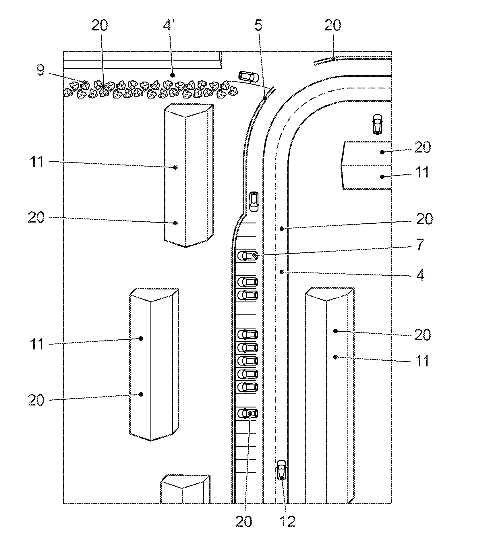
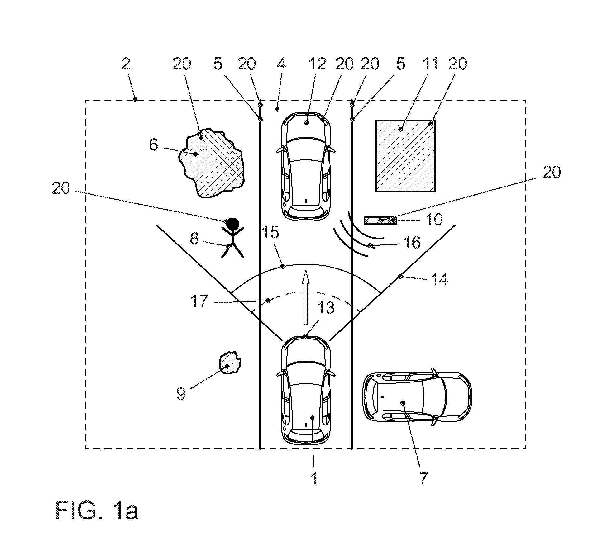
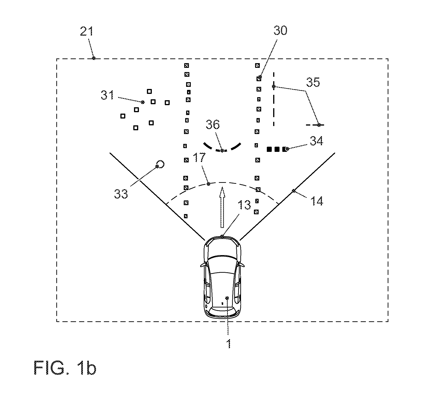
[0055]FIG. 1a shows a typical view of the environment in form of a schematic representation, such as it often can be found in daily traffic. A vehicle 1 is moving on a lane 4 in the surrounding environment 2. The vehicle 1 features a radar sensor 13, which e.g. can be affixed at the front end of the vehicle 1. The radar sensor 13 has an emission range 14 within which the objects 20 are captured. In the embodiment shown in FIG. 1, the objects 20 comprise, for example, a curb 5, a tree 6, a parked vehicle 7, a pedestrian 8, a bush 9, a metal sign 10, a house 11 and a moving vehicle 12. The opening angle 17 of the emission range 14 can, for example, be 140°, but can also be larger or smaller. In the embodiment shown in FIG. 1, the radar sensor 13 emits a radar impulse 15 which is reflected as a radar impulse response 16 by the objects 20 which lie within the opening angle 17 of the emission range 14, for example by a metal sign 10. The radar impulse response 16 is received by the radar...


PUM


Abstract

A method and a device for locating a vehicle from a fixed reference map in which objects are assigned one or more positions in the reference map. At successive points of a vehicle trajectory, in each case a radar impulse is emitted and subsequently, angle-resolved and time-resolved measurements of the radar impulse response are performed. Object positions are identified in the environment surrounding the vehicle from the radar impulse response, the current identified object positions forming an environment map. The vehicle position is identified in the reference map by comparing the environment map to the reference map, the reference map being created from the identified positions and is continuously updated. An object classification for the identified object positions in the current environment map and/or reference map is performed and the identification of the vehicle position is performed while taking the object classification into account.

Description

[0001]This nonprovisional application claims priority under 35 U.S.C. §119(a) to German Patent Application No. 10 2014 223 363.1, which was filed in Germany on Nov. 17, 2014, and which is herein incorporated by reference.BACKGROUND OF THE INVENTION[0002]1. Field of the Invention[0003]The invention relates to a method and device for improved localization of a vehicle from a stationary reference map.[0004]2. Description of the Background Art[0005]Systems are used in vehicles, in particular motor vehicles, which require information about the existence of objects in the environment surrounding the vehicle, as well as information on the position and dimension of said vehicle. Information on a vehicle's surroundings, in particular to distinguish between streets, open spaces and obstacles, is necessary for navigating in an unknown area. It can also be used as an input parameter for autonomous assistance systems such as automatic parking aids or parking assistance systems, brake assists and...

Claims


Application Information

Patent Timeline
Patent Type & Authority Applications(United States)
IPC IPC(8): G01S13/06G01S7/41G01S13/931
CPCG01S7/41G01S13/06G01S13/89G01S7/411G01S7/415G01S13/42G01S13/931G01S2013/93271G01S2013/932
Inventor BUESCHENFELD, TORSTENMAX, STEPHANURBANBROSIG, STEFAN
Owner VOLKSWAGEN AG
Why Eureka
Try Eureka