Autonomous driving vehicle system

a technology of autonomous driving and vehicle system, applied in the direction of distance measurement, process and machine control, instruments, etc., can solve the problems of insufficient warning, difficulty in knowing the distance and speed relative to the following vehicle, etc., and achieve the effect of reducing the possibility of collision

Active Publication Date: 2016-05-19
TOYOTA JIDOSHA KK
View PDF2 Cites 70 Cited by
  • Summary
  • Abstract
  • Description
  • Claims
  • Application Information

AI Technical Summary

Benefits of technology

[0007]The present invention provides an autonomous driving vehicle system that can reduce the possibility of collision with a following vehicle.
[0009]In the autonomous driving vehicle system in the above aspect, the warning light is turned on before the vehicle applies the brake to let the driver of a following vehicle know earlier that the vehicle will apply the brake. This can reduce the possibility of collision with the following vehicle.
[0011]According to the above configuration, because the braking tends to be applied with higher deceleration as the emergency level that is set is higher, it is preferable to signify the braking of the vehicle to the driver of the following vehicle early. In this case, the above-described effect that the possibility of collision with the following vehicle is reduced is remarkable.
[0013]According to the above configuration, when it is determined that the collision possibility is lower than the upper limit threshold and is higher than the lower limit threshold, the vehicle travels autonomously according to a braking postponed travel plan that performs the postponed braking in which the start of the braking is delayed as compared to the start of the braking that is performed when the collision possibility is equal to or higher than the upper limit threshold. This allows the vehicle to travel without wasting the travel time.
[0023]According to the above configuration, the light turn-on start time can be set earlier as the time to collision is shorter.

Problems solved by technology

According to the conventional technology described above, it may be difficult to know the distance and speed relative to the following vehicle, for example, when the vehicle turns right or left at an intersection or travels through a curve.
This sometimes results in an inappropriate warning to the following vehicle.

Method used


Image

  • Autonomous driving vehicle system
  • Autonomous driving vehicle system
  • Autonomous driving vehicle system

Examples


second embodiment

[0145]This embodiment may be applied to the That is, it is possible that the autonomous driving vehicle system 300 further includes the emergency level setting unit 21 and the constraint condition setting unit 22 (see FIG. 6) and that the traveling plan generation unit 14 has the above-described function in the autonomous driving vehicle system 200.

[0146]Next, a fourth embodiment is described. In the description of this embodiment, only the parts differing from those in the first embodiment are described.

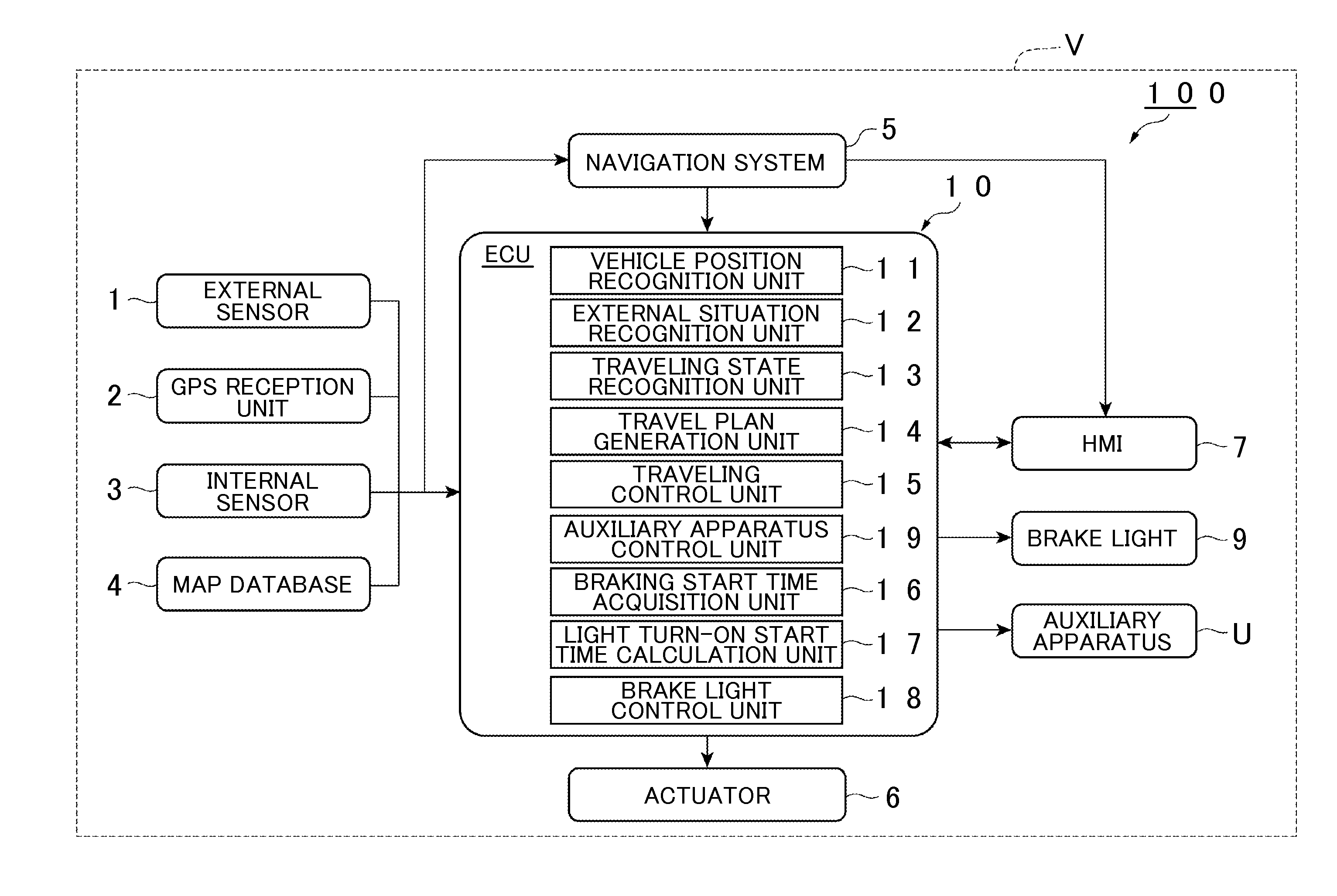
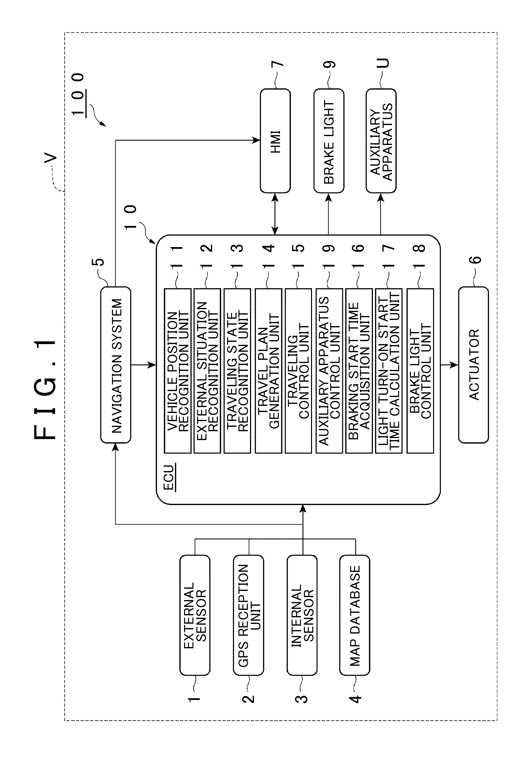
[0147]FIG. 15 is a block diagram showing the ECU 10 of an autonomous driving vehicle system 400 in the fourth embodiment. FIG. 16 is a flowchart showing the brake light turn-on processing in the autonomous driving vehicle system shown in FIG. 15. As shown in FIG. 15, the autonomous driving vehicle system 400 in this embodiment differs from that in the first embodiment in that the ECU 10 includes a correction coefficient setting unit 41 used to set a correction coefficient k.

[0148]T...

first embodiment

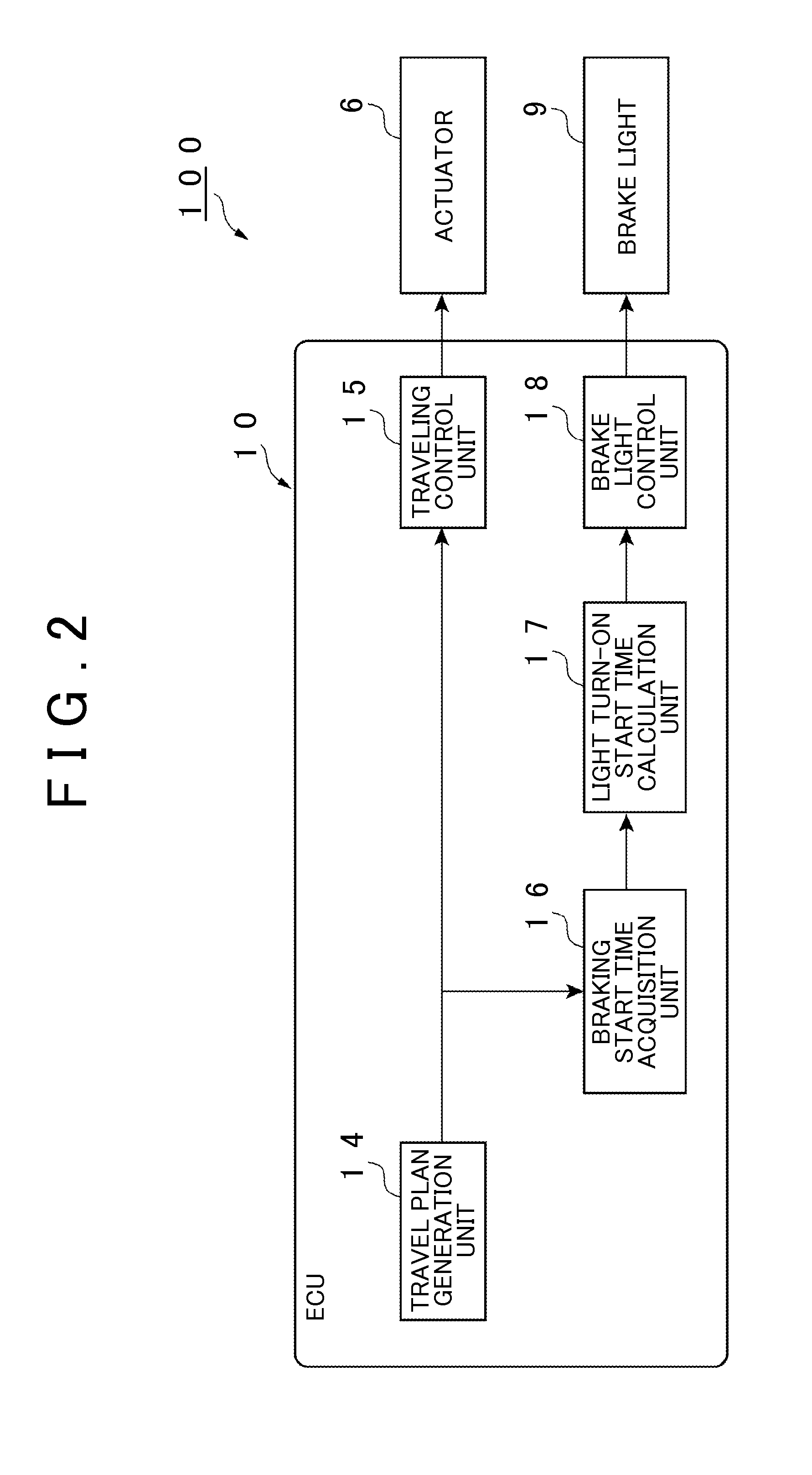
[0152]When calculating the light turn-on start time ton, the light turn-on start time calculation unit 17 calculates the lead time H′ generated by multiplying the correction coefficient k, which is set by the correction coefficient setting unit 41, by the base lead time H0. The base lead time H0 is a time that is set in advance. In this calculation, the lead time H, calculated in the same manner as in the first embodiment, is set as the base lead time H0. The light turn-on start time calculation unit 17 calculates the light turn-on start time ton that is earlier than the braking start time tv by the lead time H′. For example, in the example shown in FIG. 3A, the light turn-on start time calculation unit 17 calculates the lead time H′ using expression (3) given below.

k×((v1−v0) / an)−((v1−v0) / as)  (3)

[0153]As shown in FIG. 16, the correction coefficient setting unit 41 in the autonomous driving vehicle system 400 sets the correction coefficient k, which will be applied in the braking a...

fifth embodiment

[0167]This embodiment may be applied to the That is, it is possible that the autonomous driving vehicle system 600 further includes the adjacent lane state recognition unit 51 (see FIG. 17A) and that the correction coefficient setting unit 41 has the above-described function in the autonomous driving vehicle system 500.

[0168]Next, a seventh embodiment is described. In the description of this embodiment, only the parts differing from those in the fourth embodiment are described.

[0169]FIG. 18A is a block diagram showing the ECU 10 of an autonomous driving vehicle system 700 in the seventh embodiment. As shown in FIG. 18A, the autonomous driving vehicle system 700 in this embodiment differs from that in the fourth embodiment in that the ECU 10 includes a road surface friction coefficient estimation unit 71.

[0170]The road surface friction coefficient estimation unit 71 estimates the road surface friction coefficient of a road surface on which the vehicle V travels. To estimate the road...


PUM


Abstract

An autonomous driving vehicle system includes: a surrounding information detection unit that is configured to detect surrounding information on a vehicle; and at least one electronic control unit including: a travel plan generation unit configured to generate a travel plan along a pre-set target route based on the surrounding information and map information; a traveling control unit configured to autonomously control a traveling of the vehicle based on the travel plan; and a warning light control unit configured to turn on a warning light earlier than a start time of a braking of the vehicle in the travel plan, the warning light informing a following vehicle about the braking.

Description

INCORPORATION BY REFERENCE[0001]The disclosure of Japanese Patent Application No. 2014-234582 filed on Nov. 19, 2014 including the specification, drawings and abstract is incorporated herein by reference in its entirety.BACKGROUND OF THE INVENTION[0002]1. Field of the Invention[0003]The present invention relates to an autonomous driving vehicle system.[0004]2. Description of Related Art[0005]Conventionally, as described in Japanese Patent Application Publication No. 2014-085711 (JP 2014-085711 A), a brake control device is known that includes an arithmetic unit that calculates the time to collision based on the relative distance and the relative speed between the vehicle and a following vehicle and a warning unit that issues a warning to the following vehicle based on the comparison between the time to collision and the warning threshold.[0006]According to the conventional technology described above, it may be difficult to know the distance and speed relative to the following vehicl...

Claims


Application Information

Patent Timeline
Patent Type & Authority Applications(United States)
IPC IPC(8): G05D1/00B60Q1/44G01C21/34
CPCG05D1/0088B60Q1/44G01C21/34B60W30/09
Inventor ICHIKAWA, KENTAROKINDO, TOSHIKISAKAI, KATSUHIROHARADA, MASAHIROURANO, HIROMITSU
Owner TOYOTA JIDOSHA KK
Why Eureka
Try Eureka