Short-circuit ring for an electrical asynchronous machine, composed of partial ring segments

a technology of short-circuit rings and asynchronous machines, applied in the direction of synchronous motors, dynamo-electric machines, electrical apparatus, etc., can solve the problems of high electrical resistance losses, high production costs, and inability to cast short-circuit rings with such a large number of grooves, and achieve low cost, low electrical resistance losses, and easy production of short-circuit rings.

Active Publication Date: 2016-05-19
ROBERT BOSCH GMBH
View PDF4 Cites 9 Cited by
  • Summary
  • Abstract
  • Description
  • Claims
  • Application Information

AI Technical Summary

Benefits of technology

[0012]Specific embodiments of the present invention advantageously enable provision of a short-circuit ring for an electrical asynchronous machine in such a way that the short-circuit ring can be produced eas

Problems solved by technology

However, the larger the diameter of a rotor of an asynchronous machine that is to be provided with a squirrel cage is, the more expensive it is, as a rule, to manufacture the short-circuit rings.
A casting of short-circuit

Method used


Image

  • Short-circuit ring for an electrical asynchronous machine, composed of partial ring segments
  • Short-circuit ring for an electrical asynchronous machine, composed of partial ring segments
  • Short-circuit ring for an electrical asynchronous machine, composed of partial ring segments

Examples


Embodiment Construction

[0035]The Figures are merely schematic and are not to scale. Identical reference characters designate identical components, or components having identical function.

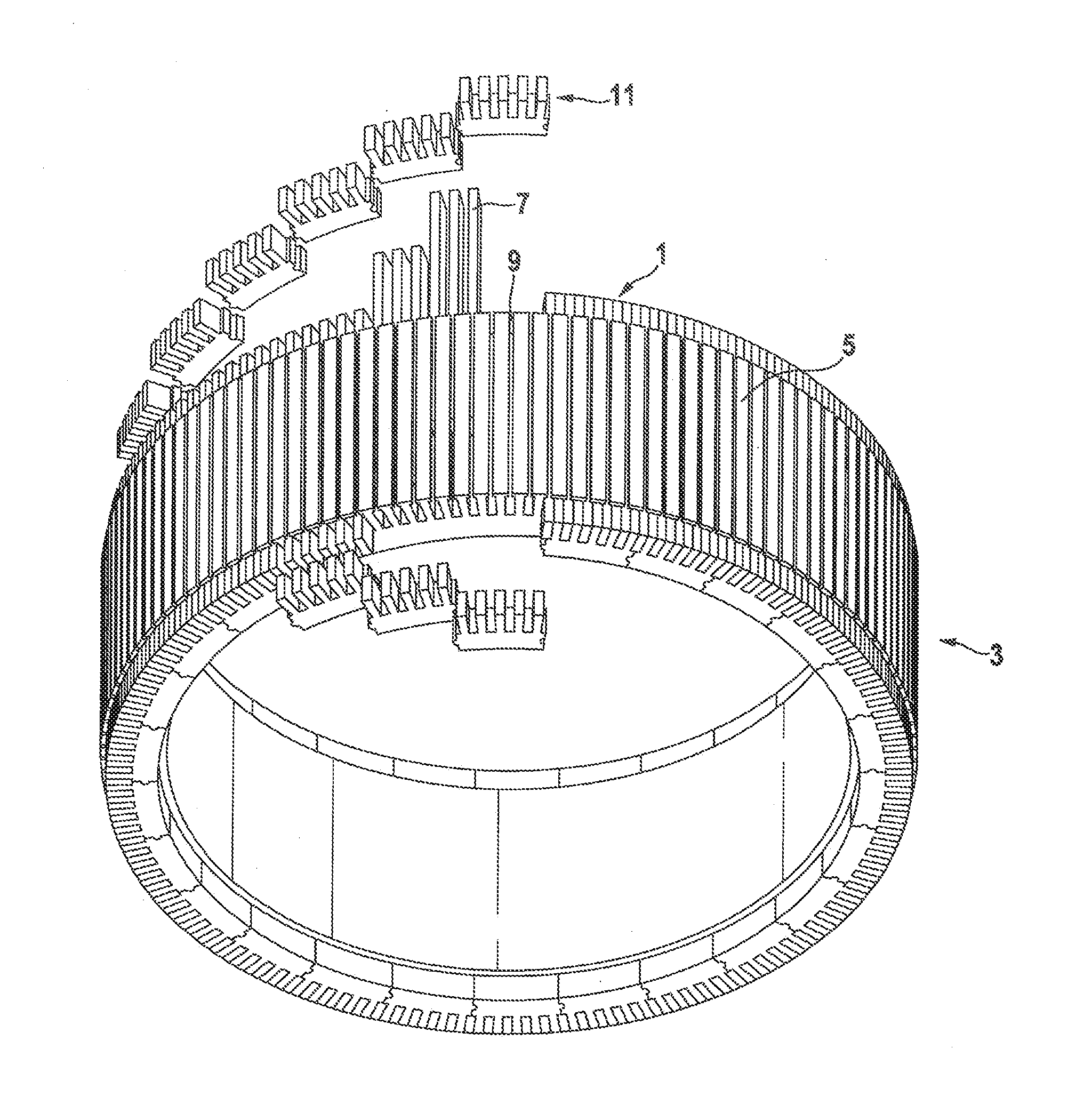
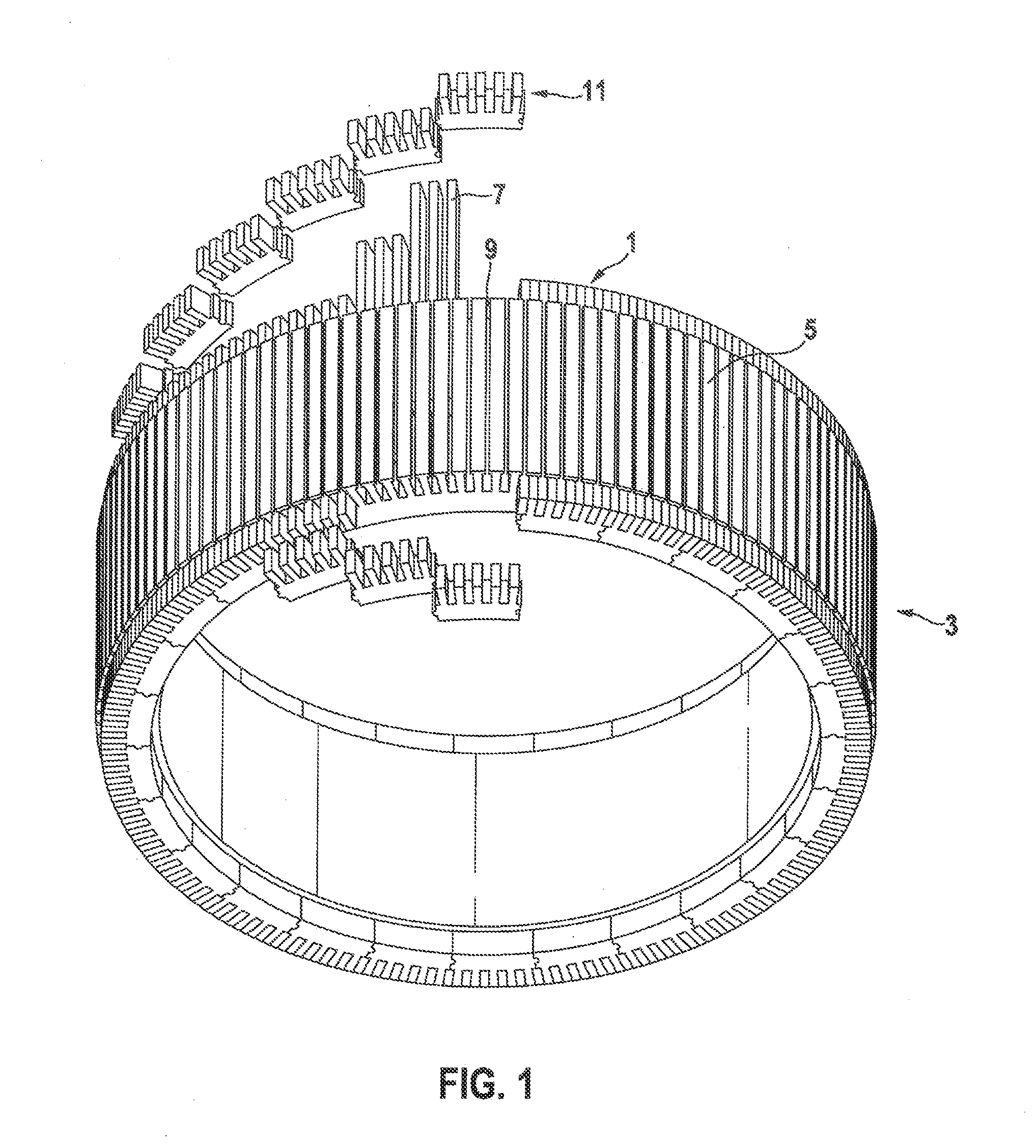
[0036]FIG. 1 shows a rotor 3 for an electrical asynchronous machine according to a specific embodiment of the present invention. Rotor 3 has an essentially cylindrical rotor body 5 on whose outer side there is fashioned a large number of grooves 9 running in the longitudinal direction. Rotor body 5 itself can be made of a soft magnetic material. On rotor body 5 there is situated a squirrel cage that is made up of oblong rods 7 and two short-circuit rings 1. The oblong rods are placed into grooves 9 of rotor body 5 and axially protrude therefrom. The two short-circuit rings 1 are situated on the two axial ends of rotor body 5. Short-circuit rings 1 also have recesses 13 in the form of grooves that can accommodate the ends of rods 7 protruding past rotor body 5. Rods 7, configured at a distance from one another along the ci...


PUM


Abstract

A short-circuit ring for a rotor of an electrical asynchronous machine is circular and has along its circumference a multiplicity of recesses extending in the axial direction, into which rods of a rotor cage of the asynchronous machine can be placed. The short-circuit ring is assembled from a plurality of partial ring segments.

Description

BACKGROUND OF THE INVENTION[0001]1. Field of the Invention[0002]The present invention relates to electrical asynchronous machines, and in particular to a short-circuit ring for an electrical asynchronous machine.[0003]2. Description of the Related Art[0004]Due in particular to their robustness and reliability, electrical asynchronous machines are used for a large number of industrial applications. Currently, electrical asynchronous machines that have a so-called squirrel cage on the rotor are being further developed in particular for use in electric or hybrid vehicles, because in such asynchronous machines, in contrast to synchronous machines, magnets do not have to be used in the rotor, so that very expensive rare earth permanent magnets that can be used for this purpose can be done without.[0005]In an electrical asynchronous machine, during operation high electrical currents are induced in a squirrel cage provided on a rotor, and on the basis of these currents strong magnetic fiel...

Claims


Application Information

Patent Timeline
IPC IPC(8): H02K17/16
CPCH02K17/165H02K2213/12
Inventor BERGER, THOMASKELLETER, ARNDTLAUE, HARALD
Owner ROBERT BOSCH GMBH
Why Eureka
Try Eureka