Electroacoustic Transducer and Acoustic Resistor

Active Publication Date: 2016-05-19
AUDIO-TECHNICA
View PDF8 Cites 17 Cited by
  • Summary
  • Abstract
  • Description
  • Claims
  • Application Information

AI Technical Summary

Benefits of technology

[0009]The electroacoustic transducer of the present invention has a variable acoustic impedance and exhibits an ex

Problems solved by technology

However, an electroacoustic transducer particularly in the form of a headphone set has an insufficient volume of a back space due to demands for design and size reduction in some cases.
Such an electroacoustic transducer with an insufficient volume of a back space restricts air stiffness and acoustic design of mass components.
Small electroacoustic transducers, such as headphone sets, earphones, and tableto

Method used


Image

  • Electroacoustic Transducer and Acoustic Resistor
  • Electroacoustic Transducer and Acoustic Resistor
  • Electroacoustic Transducer and Acoustic Resistor

Examples


Example

[0018]Embodiments of an electroacoustic transducer of the present invention will now be described with reference to the attached drawings.

Headphone Set (1)

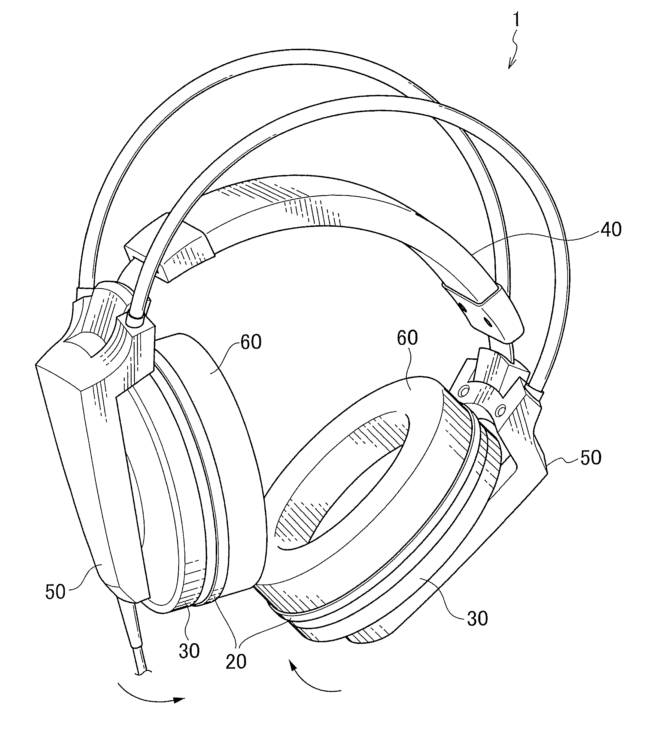
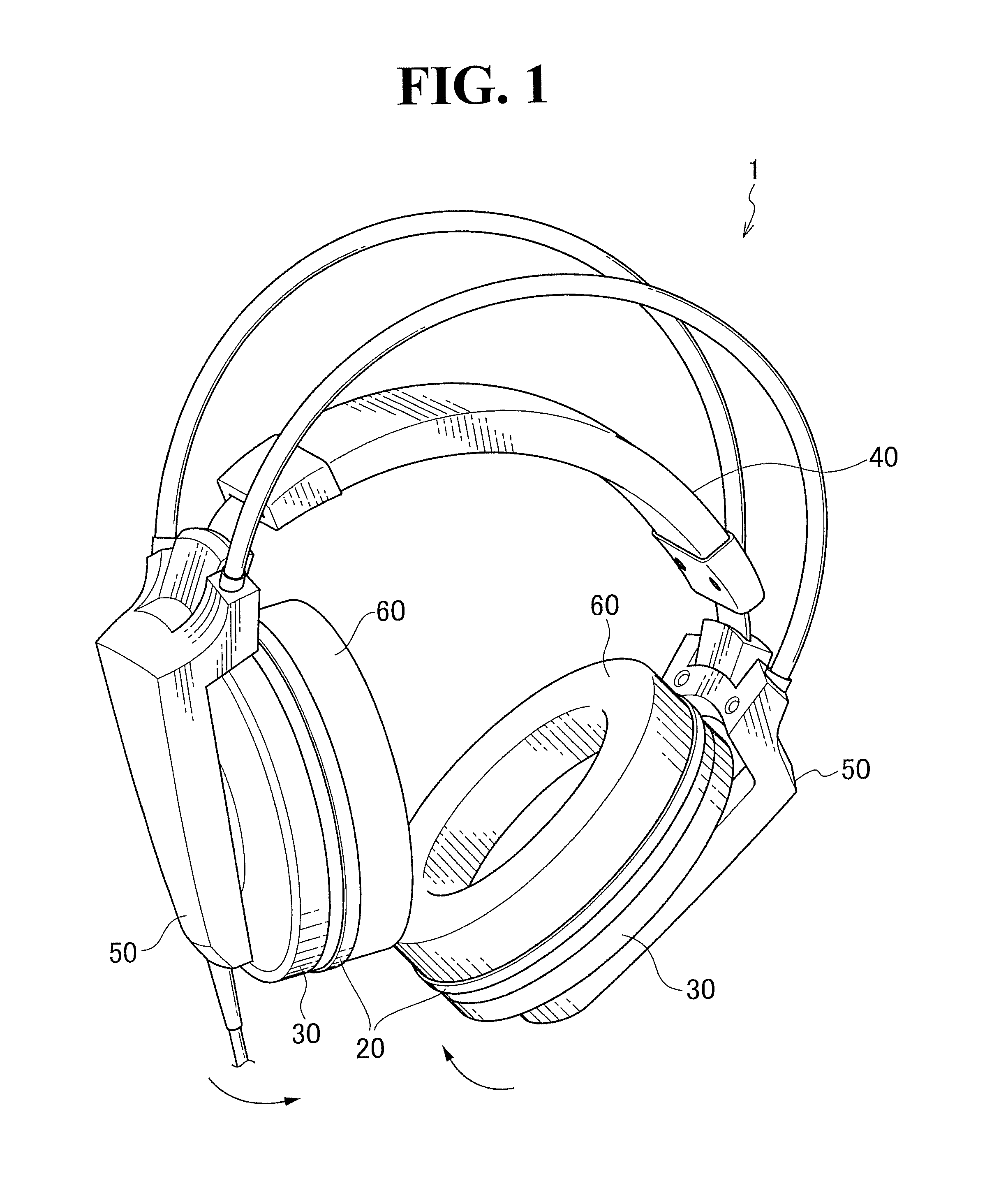
[0019]With reference to FIGS. 1 to 3, a headphone set 1, which is an embodiment of an electroacoustic transducer of the present invention, includes driver units 10, which are driven in response to electrical signals and output sound, and baffle assemblies 20 in which the driver units 10 are mounted. The headphone set 1 also includes housings 30 attached to the respective baffle assemblies 20 to form headphone units and a headband 40 for holding the headphone set 1 on the head of a user. The headphone set 1 also includes supports 50 and ear pad 60. Each support 50 is connected to the headband 40 and holds the corresponding housing 30. The ear pads 60 come into contact with the ear regions of the user in use. The headphone units each have a substantially oval-cylindrical shape to cover the ear regions of the user.

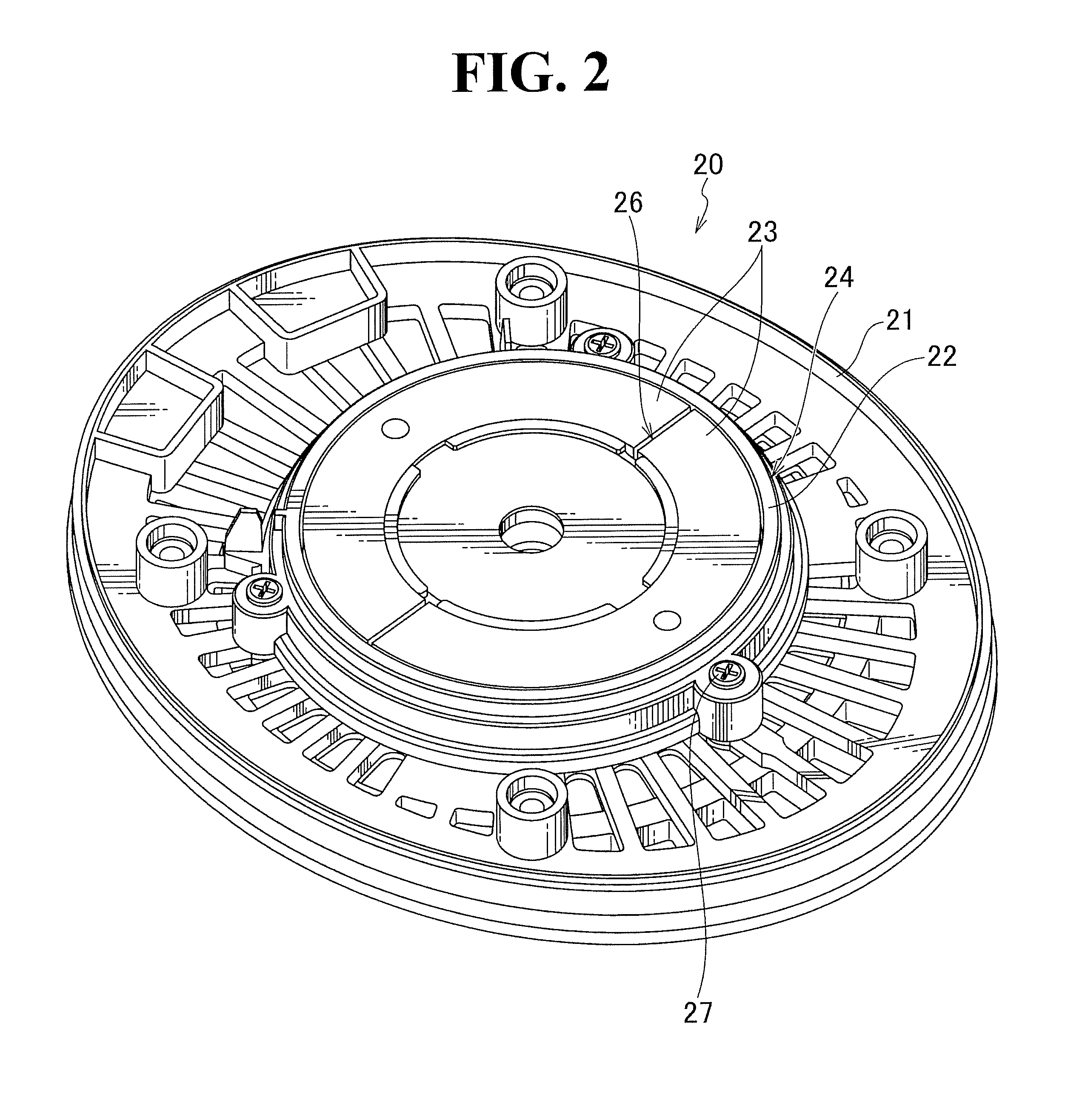
[0020]FIG. 2 is a p...


PUM


Abstract

An electroacoustic transducer includes a driver, a diaphragm 13 driven to vibrate by the driver and emitting sound, a baffle 22 holding the driver and the diaphragm 13, first openings 25 extending through the baffle 22, an acoustic resistor 23 disposed on the back side of the baffle 22, and second openings 26 extending from the front side to the back side of the acoustic resistor 23. The baffle 22 is provided on the back side of the diaphragm 13. The first openings 25 are provided in the baffle 22. The second openings 26 are each disposed above one of the first openings 25 in the acoustic resistor 23. The electroacoustic transducer exhibits an excellent frequency response even if a sufficient volume of a space is not provided on the back side of the diaphragm 13.

Description

TECHNICAL FIELD[0001]The present invention relates to electroacoustic transducers and acoustic resistors.BACKGROUND ART[0002]Electroacoustic transducers, such as headphone sets and loudspeakers, are known that convert electrical signals into sounds. Such an electroacoustic transducer includes a driver unit composed of a driver and a diaphragm. To achieve stable operation of the driver unit, required is a space having a sufficient volume and disposed on the side opposite to the side through which the sound emitted from the diaphragm passes. The space is defined by a housing covering the driver unit. The side opposite to the sound emitting side is referred to as a “back side”. The space on the back side in the housing is referred to as a “back space”.[0003]However, an electroacoustic transducer particularly in the form of a headphone set has an insufficient volume of a back space due to demands for design and size reduction in some cases. Such an electroacoustic transducer with an ins...

Claims


Application Information

Patent Timeline
IPC IPC(8): H04R1/28
CPCH04R1/2849H04R1/1008
Inventor HONDA, YOJITSUIHIJI, KENZOTANOUE, KOICHIROARAI, KENJI
Owner AUDIO-TECHNICA
Why Eureka
Try Eureka