High-resistance broadband attenuation circuit and oscilloscope using same

An attenuation circuit and digital oscilloscope technology, applied in the field of high-resistance broadband attenuation circuits and digital oscilloscopes, can solve the problems of less grounding points of the voltage divider circuit, large influence of the voltage divider network, and large signal overshoot, etc., and achieves good attenuation performance and frequency. Good response and little signal overshoot

Active Publication Date: 2011-05-11
RIGOL
View PDF6 Cites 15 Cited by
  • Summary
  • Abstract
  • Description
  • Claims
  • Application Information

AI Technical Summary

Problems solved by technology

[0007] High-frequency signals easily pass through the PCB and inside the relay, crosstalking from one side of the relay to the other, making the amplitude of the high-frequency component at the output end larger and the signal overshoot larger
[0008] 2. The voltage divider network is greatly affected by the equivalent series inductance (ESL)
[0009] Since the compensation of the voltage divider network to the ground is only R5, C2, and C3, when the frequency is high, the influence of the equivalent series inductance of the resistors R5, C2, and C3 cannot be ignored, and it is easy to cause excessive ringing on the rising edge of the signal. make the rising edge slower and lower the bandwidth
[0010] 3. There are few ground points in the voltage divider circuit, and the high-frequency signal component is not sufficiently released to the ground, causing the output signal to overshoot too much

Method used


Image

  • High-resistance broadband attenuation circuit and oscilloscope using same
  • High-resistance broadband attenuation circuit and oscilloscope using same
  • High-resistance broadband attenuation circuit and oscilloscope using same

Examples


Embodiment Construction

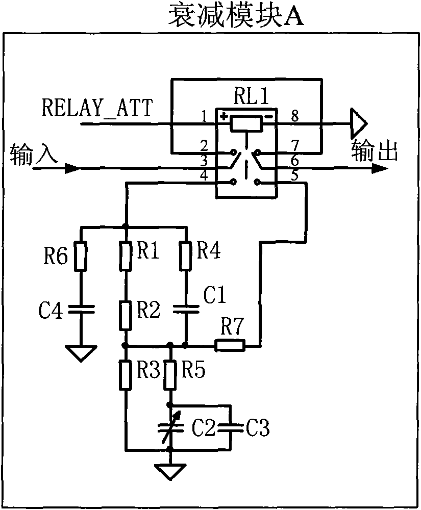
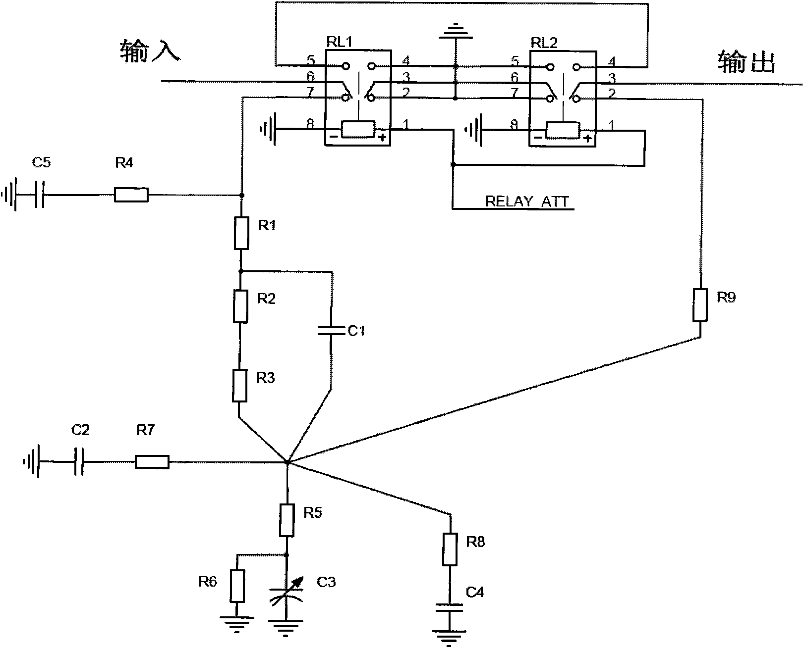
[0036] Such as image 3 As shown, the high-impedance broadband attenuation circuit provided by the present invention is composed of two double-pole double-throw relays RL1, RL2 and a plurality of resistance-capacitance elements. Wherein, the control ends of the relays RL1 and RL2 are connected together and controlled by the RELAY_ATT signal. Double-pole double-throw relays RL1 and RL2 use only one side of the relay, and the other side of the relay is grounded. In this embodiment, RL1 uses a relay composed of pins 5, 6, and 7 on the left, and RL2 uses a relay composed of pins 2, 3, and 4 on the right. These two relays are conversion type (Z-type) relays with one moving contact and two static contacts, among which pin3 and pin6 are moving contacts. pin2, 4, 5, 7 are static contacts. There is generally a metal arm on pin3 and pin6, which is usually connected to pin2 and pin7. If the coil between pin1 and pin8 is energized, the magnetic force generated will attract the metal ar...


PUM


Abstract

The invention discloses a high-resistance broadband attenuation circuit and also discloses a digital oscilloscope using the high-resistance broadband attenuation circuit. The high-resistance broadband attenuation circuit comprises a first relay, a second relay, a high-frequency compensation circuit, a first RC (Remote Control) network and a second RC network. The moving contact of the first relay is connected with an input end, the moving contact of the second relay is connected with an output end, and the control ends of the first relay and the second relay are connected together; the second static contact of the first relay is connected with the high-frequency compensation circuit and the first RC network, the other end of the high-frequency compensation circuit is grounded, and the other end of the first RC network is connected with the second RC network; and one end of the second RC network is grounded, and the other end of the second RC network is connected with the second static contact of the second relay through a resistor. The influence of equivalent series inductance at a high frequency on the high-resistance broadband attenuation circuit is quite small; a high-frequency signal component has sufficient release for the ground; and the bandwidth of an output signal is large, the signal overshoot is small, and the frequency response is good.

Description

technical field [0001] The invention relates to a high-resistance broadband attenuation circuit used in a digital oscilloscope, and also relates to a digital oscilloscope using the high-resistance broadband attenuation circuit, belonging to the technical field of electromagnetic measuring instruments. Background technique [0002] Digital oscilloscope is a new type of oscilloscope composed of data acquisition unit, A / D converter, scanning oscillator, etc. It plays a very important role in scientific research and production. In the process of digital oscilloscope collecting signals, the analog signal input needs to be attenuated and amplified by a certain number of times according to the signal amplitude, so that the signal is in a signal range suitable for A / D converter sampling, and displayed on the oscilloscope screen Get a waveform suitable for observation. The attenuator at the input end of the analog signal can increase the range of the oscilloscope signal input. There...

Claims


Application Information

Patent Timeline
Patent Type & Authority Applications(China)
IPC IPC(8): G01R1/00G01R13/02
Inventor 王悦王铁军李维森
Owner RIGOL
Why Eureka
Try Eureka