Capacitor microphone

Active Publication Date: 2010-12-30
AUDIO-TECHNICA
View PDF2 Cites 4 Cited by
  • Summary
  • Abstract
  • Description
  • Claims
  • Application Information

AI Technical Summary

Benefits of technology

[0013]The present invention is made in view of the above. An object of the present invention is to provide a capacitor microphone having advantages of both large and small capacitor microphone units. More specifically, the present invention provides a capacitor microphone that has excellent frequency response in a high frequency domain and excellent S / N ratio.
[0016]According to the present invention, if each of the capacitor microphone units is small, as an acoustic mechanical vibration system, the capacitor microphone units each serve as a small capacitor microphone unit having excellent directional frequency response in a high frequency domain. The capacitor microphone units are electrically connected to respective impedance converters, and the capacitor microphone units are connected in series via the impedance converters. Thus, an output voltage is multiplied by the number of capacitor microphone units connected in series. Thus, S / N ratio becomes to be high and, in accordance with this, the sensitivity becomes to be high. Accordingly, a capacitor microphone can be provided that has excellent directional frequency response up to a high frequency domain, and excellent S / N ratio.

Problems solved by technology

Unfortunately, the diaphragm therein has small area.
Thus, a small capacitor microphone has poor sensitivity and S / N ratio.
Unfortunately, the distance between a front acoustic terminal and a rear acoustic terminal is large and therefore, frequency response in high frequency range is poor.
Therefore, sensitivity is difficult to be improved.

Method used


Image

  • Capacitor microphone
  • Capacitor microphone
  • Capacitor microphone

Examples


Embodiment Construction

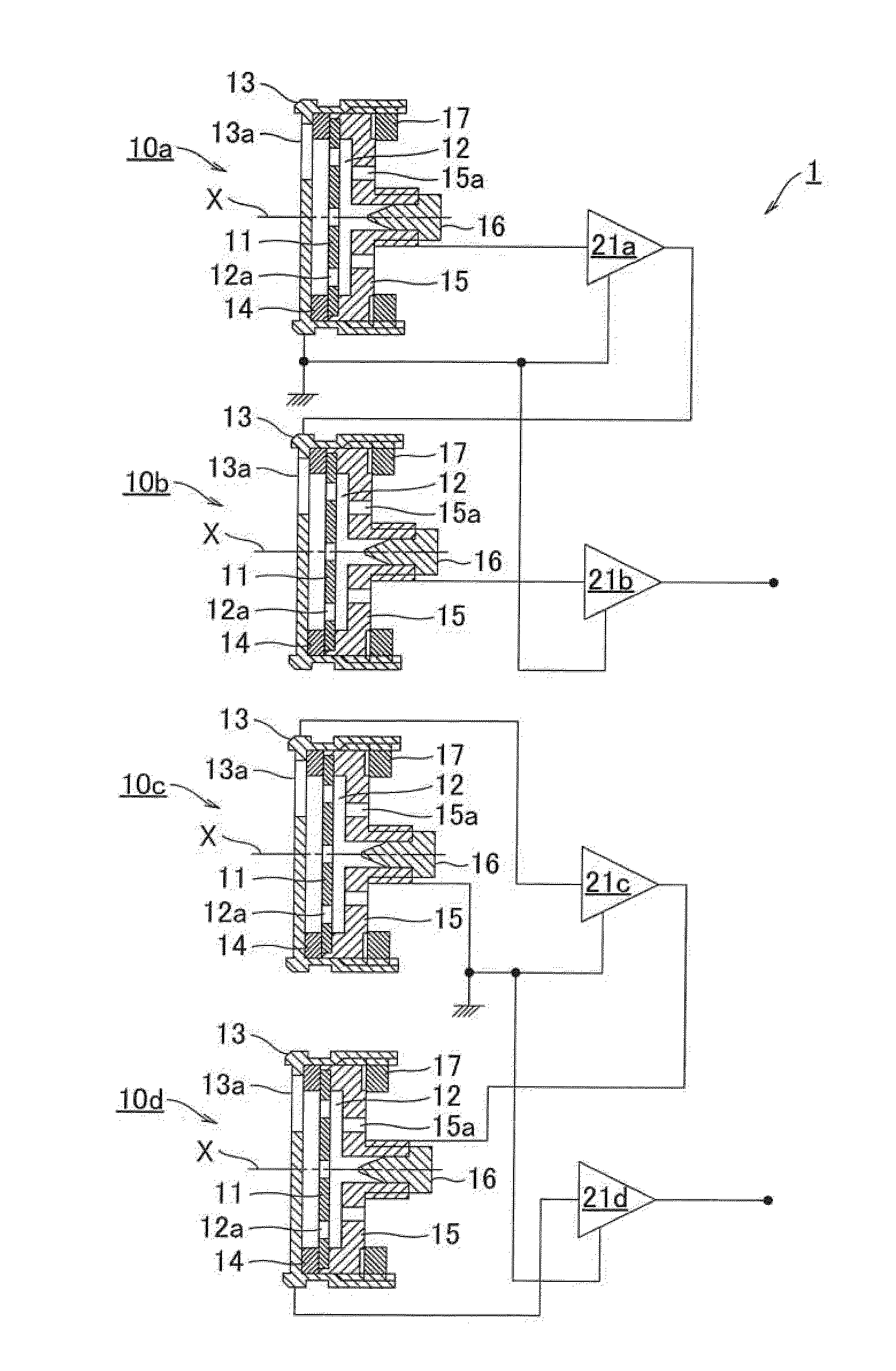
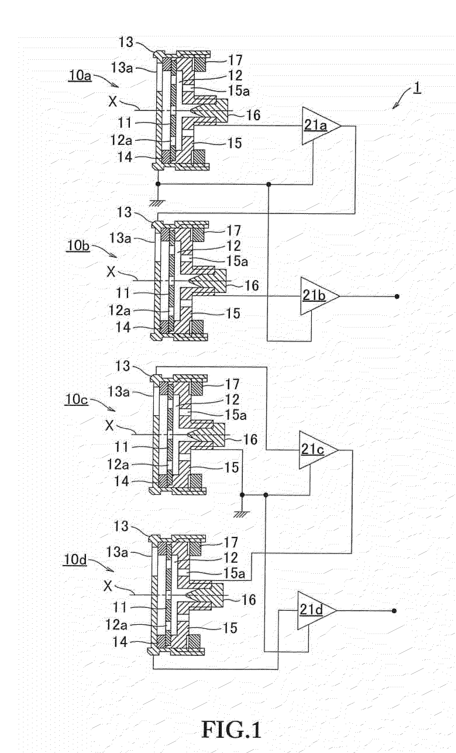
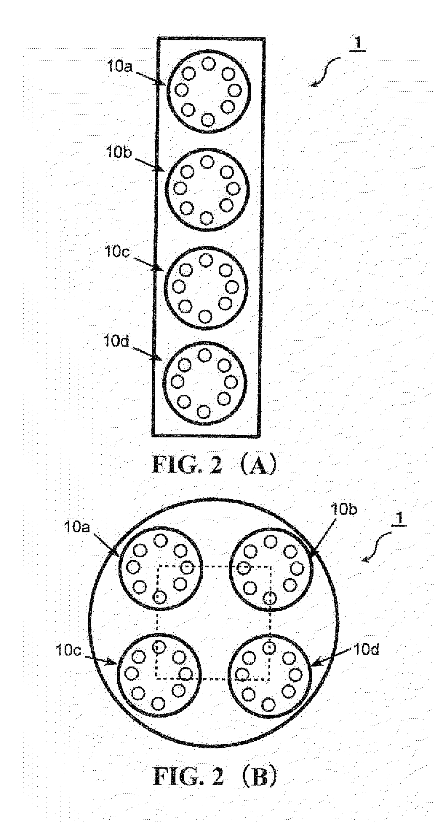
[0020]An embodiment of a capacitor microphone according to the present invention is described with reference to the accompanying drawings. FIG. 1 is a schematic cross-sectional view illustrating a structure of a capacitor microphone according to the present invention. FIGS. 2A and 2B each exemplary illustrates an arrangement of capacitor microphone units when viewed from the sound source side.

[0021]In FIG. 1, this capacitor microphone 1 is composed of a plurality of capacitor microphone units 10 (10a to 10d). The capacitor microphone units 10a to 10d are each a small capacitor microphone unit having excellent directional frequency response in a high frequency domain. The capacitor microphone units 10a to 10d have an identical structure.

[0022]Detail structure is described with reference to the capacitor microphone unit 10a in FIG. 1. The capacitor microphone unit 10a includes a diaphragm 11, a fixed pole 12, and a casing 13. The diaphragm 11 and the fixed pole 12 are provided facing ...


PUM


Abstract

Diaphragms of a plurality of capacitor microphone units are arranged in the same plane and the capacitor microphone units are connected in series to make an output from an impedance converter connected to one capacitor microphone unit drives a ground side of another capacitor microphone unit connected to the impedance converter.

Description

BACKGROUND OF THE INVENTION[0001]1. Field of the Invention[0002]The present invention relates to a capacitor microphone that has excellent directional frequency response up to a high frequency domain, and excellent sensitivity.[0003]2. Description of the Related Art[0004]Capacitor microphones have a basic configuration such as that disclosed in Japanese Patent Application Publication H2-237300. More specifically, capacitor microphones include: a capacitor microphone unit composed of a diaphragm a fixed pole that are provided facing each other via a spacer; and a sound signal output unit including an impedance converter that converts vibration of the diaphragm due to sound waves into an electrical signal as a change in capacitance.[0005]A unidirectional capacitor microphone includes: a front acoustic terminal with which sound waves from a sound source are directly applied to the front surface side of a diaphragm; and a rear acoustic terminal with which the sound waves are applied to ...

Claims


Application Information

Patent Timeline
IPC IPC(8): H04R3/00
CPCH04R19/04
Inventor AKINO, HIROSHIYOSHINO, SATOSHISHIMURA, HARUHITO
Owner AUDIO-TECHNICA
Why Eureka
Try Eureka