
Method for optimizing the control of a free turbine power package for an aircraft, and control for implementing same

a technology of free turbine power and control method, which is applied in the direction of machines/engines, instruments, analogue processes for specific applications, etc., can solve the problems of imposing then a cumbersome and expensive definition of supercharger, and the equipment which is driven together is not capable of supplying the power required for each. , to achieve the effect of reducing the excursion of lp body speed, ensuring reliability of power supply, and reducing sound level

Active Publication Date: 2016-05-26
SAFRAN HELICOPTER ENGINES
View PDF1 Cites 1 Cited by
  • Summary
  • Abstract
  • Description
  • Claims
  • Application Information

AI Technical Summary

Benefits of technology

The invention uses continuous power measurements to detect when equipment needs more power and can activate an increase in power supply. This allows for quicker response times and reduces the variation in the speed of the body, ensuring better control and reliability of the power supply. It also eliminates the need for shedding, a process that increases the distance between two components in a power transmission system.

Problems solved by technology

And the mere choice of a variable geometry of the air flow imposes then a cumbersome and expensive definition of the supercharger.
So, in case of overspeed, the equipments which are driven together are not capable any more of supplying the power required for each of them.

Method used


Image

  • Method for optimizing the control of a free turbine power package for an aircraft, and control for implementing same
  • Method for optimizing the control of a free turbine power package for an aircraft, and control for implementing same
  • Method for optimizing the control of a free turbine power package for an aircraft, and control for implementing same

Examples


Embodiment Construction

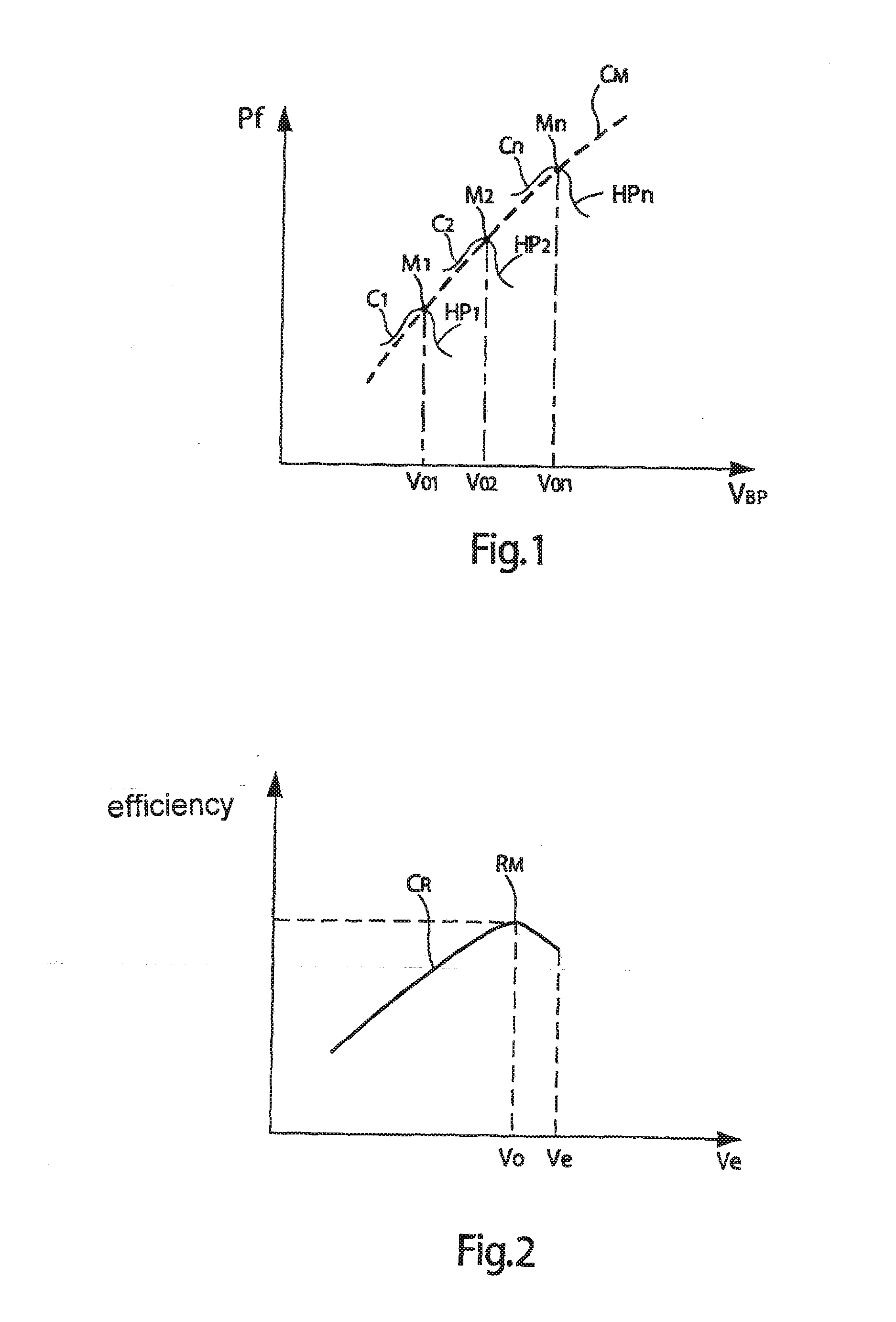
[0053]In reference to FIG. 1, curves C1 to Cn of the mechanical power supplied Pf by the LP body of a power unit fitted with a TL turbine are presented. The power Pf is represented according to the rotational speed VBP of the LP body, for a defined ambient condition—of temperature and pressure at the inlet of the LP body and for various levels of thermal power of the HP body, HP1 to HPn. Each curve C1 to Cn has a “two-horned hat” profile. The power maxima, M1 to Mn, correspond then to optimal speeds VO1, . . . , Von which are situated along an optimal curve CM. This optimal curve CM is stored so that it can be used in the regulation control unit in order to determine the amplitude of the increment by calculation.

[0054]Besides, FIG. 2 shows the efficiency curve CR for a given level of power supplied to a given equipment, here a supercharger, according to the speed Ve at which this equipment is driven. The maximal efficiency RM is obtained for an optimal speed VO close to its permissi...


PUM


Abstract

A method optimizing fuel-injection control with driving speeds of apparatuses adjusted by controlling a turbine speed according to power, and optimizing control of a free turbine power package of an aircraft, including a low-pressure body, supplying power to apparatuses and linked to a high-pressure body. The method varies the low-pressure body speed to obtain a minimum speed for the high-pressure body, so power supplied by the apparatuses remains constant. Power supplied by the apparatuses is dependent upon the apparatuses driven speed by the low-pressure body, and a speed set point of the low-pressure body is dependent upon a maximum value of minimum speeds of the apparatuses, enabling required power to be optimized, upon a positive or zero incrementation added to the speed set point of the low-pressure body to minimize speed of the high-pressure body to the apparatuses power supply.

Description

CROSS-REFERENCE TO RELATED APPLICATIONS[0001]This application is a division of U.S. application Ser. No. 13 / 817,175 filed Feb. 15, 2013, the entire contents of which is incorporated herein by reference. U.S. application Ser. No. 13 / 817,175 is a 371 of International Application No. PCT / FR11 / 051945 filed Aug. 23, 2011 and claims the benefit of priority from prior French Application No. 10 56774 filed Aug. 25, 2010.TECHNICAL FIELD[0002]The invention relates to a method for optimizing the regulation of a free-turbine power unit capable of supplying power in an aircraft, as well as a regulation control unit for implementing this method.[0003]The invention relates to free-turbine power units which are fitted in aircrafts, for example airplanes and helicopters, capable of supplying power. Notably, these units can supply power to the equipments (alternators, pumps, superchargers, air conditioning) of the aircraft, directly and / or indirectly via power transfer boxes with multiple-reduction r...

Claims


Application Information

Patent Timeline
Patent Type & Authority Applications(United States)
IPC IPC(8): F02C9/28
CPCF02C9/28F05D2270/053F05D2260/96F05D2270/02F05D2270/20F02C7/32F05D2220/329F05D2220/50F05D2270/06F05D2270/304F02C9/26
Inventor HAILLOT, JEAN-MICHEL
Owner SAFRAN HELICOPTER ENGINES
Features
  • Generate Ideas
  • Intellectual Property
  • Life Sciences
  • Materials
  • Tech Scout
  • Unparalleled Data Quality
  • Higher Quality Content
  • 60% Fewer Hallucinations
Learn More