
Image processing method and system

a processing method and image technology, applied in image enhancement, image analysis, texturing/coloring, etc., can solve problems such as impossible course, and achieve the effects of reducing medium-wave sensitivity, reducing long-wave sensitivity, and improving fidelity

Active Publication Date: 2016-05-26
APPLE INC
View PDF16 Cites 13 Cited by
  • Summary
  • Abstract
  • Description
  • Claims
  • Application Information

AI Technical Summary

Benefits of technology

The present invention provides methods for creating images that are more accessible for color-blind observers while maintaining good fidelity for color-normal observers. The resulting images are more natural and closer to the original, leading to improved visual experience for color-blind individuals. The methods can also be applied to enhance image fidelity for viewers who may have varying degrees of color-blinding.

Problems solved by technology

Of course this is impossible: a colour monitor can produce one image.

Method used


Image

  • Image processing method and system
  • Image processing method and system
  • Image processing method and system

Examples


example calculation

[0066]Let us calculate the cone response and deuteranomalous response for a given RGB image I. Here we use the superscript to index the (i,j) pixel location:

pi,j=[M+]−1αi,j Pi,j=[M]−1αi,j  (13)

[0067]We now calculate the difference image D:

Di,j=PLi,j−PMi,j  (14)

[0068]For a deuteranomalous observer D constitutes the information they cannot see (since their medium- and long-wave sensor mechanisms are almost the same, the contrast between these channels is small or zero). Let us now make a modified image:

Ji,j=MPi,j PSi,j=PSi,j+kDi,j  (15)

[0069]Where k is a user-defined scalar. We add the scaled contrast that is invisible to the deuteranope to the blue channel in the hope that this will make the invisible detail visible. In fact the difference image can be added in many ways to the cone image. Rather than adding simply to the blue channel we could add to a so-called yellow blue response (a linear combination of the cones: Y / B=L+M−2S). Alternatively, the difference could be computed by so...


PUM


Abstract

An image processing method, system and device are disclosed. In the method, sensor responses for an input image are estimated, the sensor responses including sensor responses for cone sensors including a first cone sensor set and a second, different, cone sensor set. In dependence on the sensor responses, a transform mapping for application to a source image is determined to generate a modified image.

Description

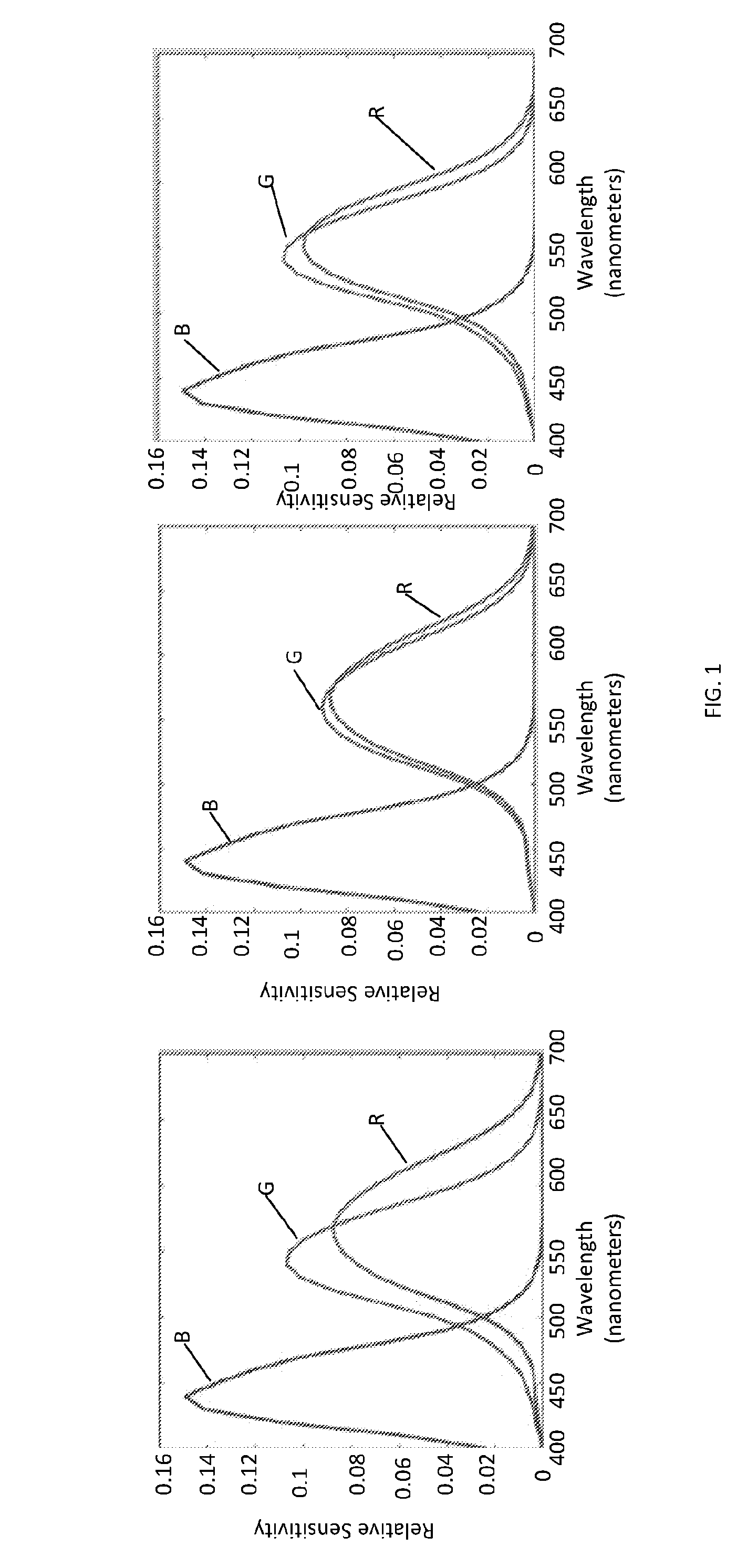
FIELD OF THE INVENTION[0001]The present invention relates to imaging processing methods and systems and also to products such as filters designed or produced to leverage results of the imaging processing methods and systems.BACKGROUND TO THE INVENTION[0002]The human visual system has 3 types of sensors: Long-, Medium- and Short-wave sensitive cone mechanisms (referred to as L, M and S, respectively). The interaction of a spectral power distribution (a light) with these sensors:Pk=∫ωC(λ)Qk(λ)dλ  (1)[0003]In (1), C(λ) denotes the spectral power distribution entering the eye, and Qk(λ) for kε{L, M, S} denotes the cone responses. The integration is over the visible spectrum co (approximately 400 to 700 Nanometres). Note here and throughout the document we adopt the convention that cone responses are vectors denoted by an uppercase P. Given (1) we can, as we show later, find the red, green and blue pixel values in an image that produce a desired colour, to match the colours in the image ...

Claims


Application Information

Patent Timeline
Patent Type & Authority Applications(United States)
IPC IPC(8): G06T5/00G06T7/40G06T7/00G06T11/00
CPCG06T5/007G06T11/001G06T2207/10024G06T7/0081G06T7/408G06T7/11G06T7/90G06T5/90
Inventor FINLAYSON, GRAHAMMONTAGNA, ROBERTO
Owner APPLE INC
Learn More