
Base station and communication control method

a communication control and base station technology, applied in sustainable communication technology, climate sustainability, high-level techniques, etc., can solve the problems of difficult to achieve energy saving restrict the deterioration of service quality, and reduce power consumption of a base station. , the effect of reducing the power consumption of a base station

Inactive Publication Date: 2016-05-26
KYOCERA CORP
View PDF5 Cites 2 Cited by
  • Summary
  • Abstract
  • Description
  • Claims
  • Application Information

AI Technical Summary

Benefits of technology

The patent text describes a method for reducing power consumption of a mobile communication base station while maintaining service quality. This is achieved by halting operation of a cell managed by the base station and sending a notice to neighboring base stations about the energy saving transition. The method allows for a gradual reduction of power consumption without disrupting communication with user terminals connected to the base station. This can be useful in reducing energy costs and improving the overall performance of the network.

Problems solved by technology

It is difficult to achieve energy saving of a base station while restraining deterioration of the service quality.

Method used

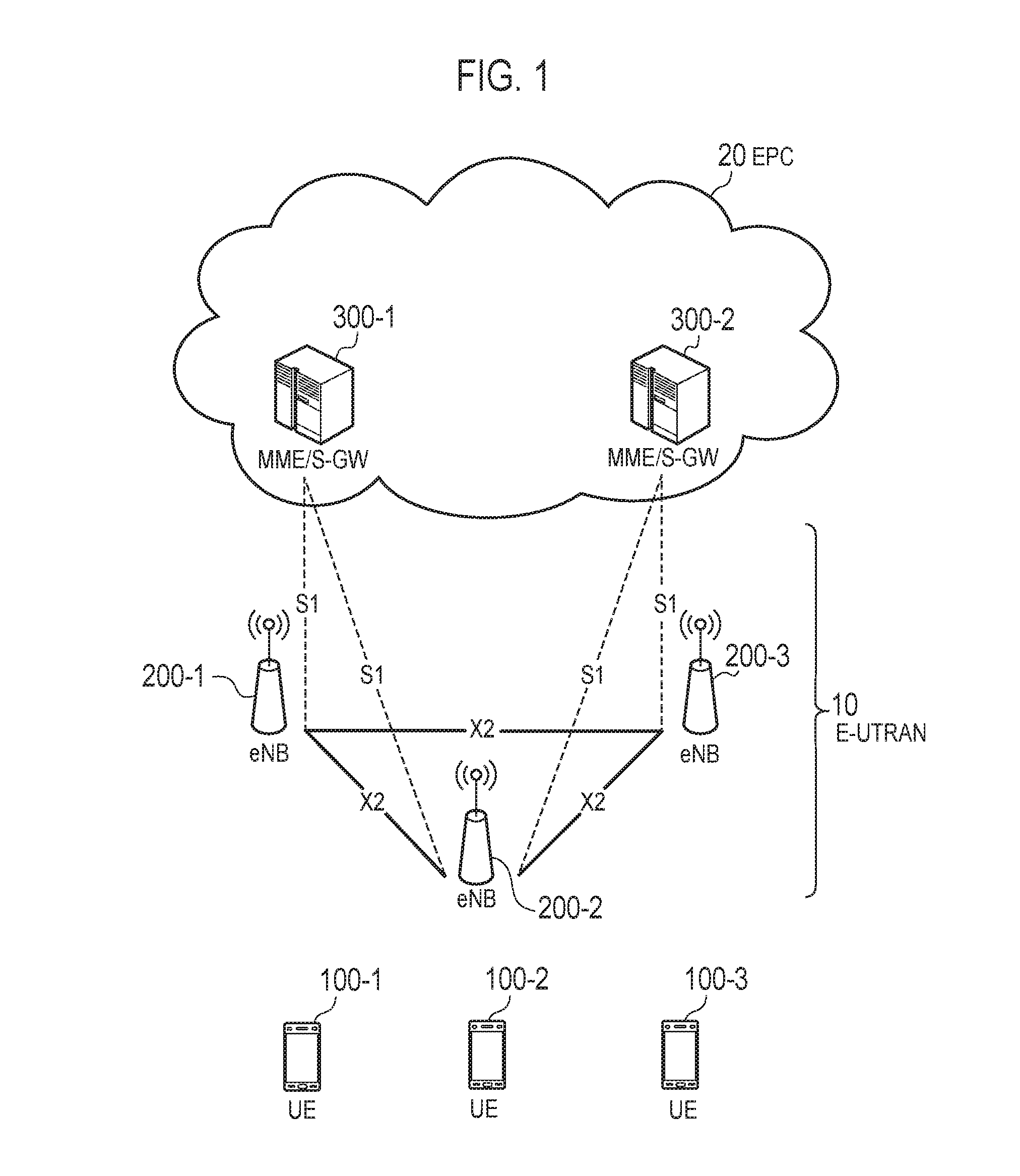
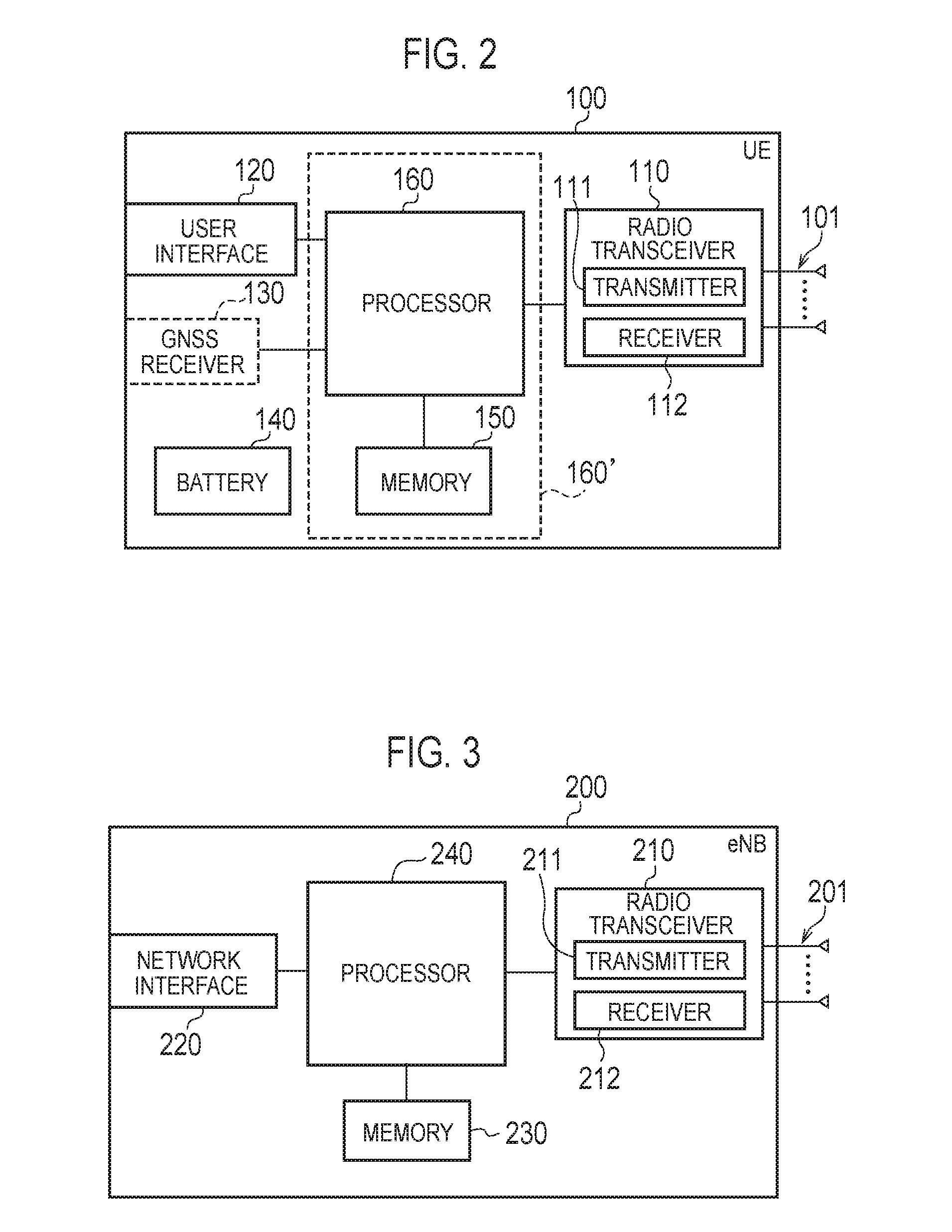

Image

  • Base station and communication control method
  • Base station and communication control method
  • Base station and communication control method

Examples


first embodiment

Modification of First Embodiment

[0104]According to the first embodiment, on the basis that the reason for handover rejection is “No Radio Resources Available,” the eNB 200-1 having received the rejection notice (Handover Preparation Failure) determines that no further handover is possible and ends the transition operation.

[0105]Instead of immediately ending the transition operation, the eNB 200-1 may retry the transition operation upon lapse of a certain time period after having determined that handover is not possible. When the load level of the eNB 200-2 has decreased during the aforementioned certain time period, continuation of the transition operation is possible. The aforementioned certain time period may be set to a constant value or a variable (setting may be made by EPC 20 or the eNB 200-2).

[0106]Instead of determining an increase in the load level of the eNB 200-2 based on the rejection notice (Handover Preparation Failure), the Resource Status Reporting procedure (see TS3...

second embodiment

Modification of Second Embodiment

[0134]FIG. 13 is an operation sequence diagram according to the second embodiment. As described in the first embodiment, assuming that the eNB 200-1 changes the energy saving method in order, it is preferable to handover cell edge the UE while the handover parameter is updated in order. In this case, it is preferable to notify the handover parameter from the eNB 200-1 to the eNB 200-2 a plurality of times either periodically or by using a change of the energy saving method as a trigger.

[0135]In the example of FIG. 13, firstly, the eNB 200-1 transmits an energy saving transition notice (Cell Transition Indication) to the eNB 200-2 (step S301). Thereafter, upon each change of the energy saving method (steps S302, S304, S306, S308), negotiation is performed between the eNB 200-1 and the eNB 200-2 (steps S303, S305, S307). In the negotiation, the eNB 200-1 notifies the eNB 200-2 of an updated handover parameter.

Other Embodiments

[0136]In the abovementione...


PUM


Abstract

A base station (eNB 200-1) according to a first aspect is a base station for use in a mobile communication system. The base station includes a controller configured to perform an energy saving operation for reducing power consumption of the base station while enabling communication between the base station and user terminals connected to the base station. Prior to performing the energy saving operation, the controller transmits, to a neighboring base station (eNB 200-2), an energy saving transition notice (Cell Transition Indication) that indicates transition to the energy saving operation.

Description

TECHNICAL FIELD[0001]The present invention relates to a base station and communication control method for use in a mobile communication system.BACKGROUND ART[0002]The 3rd Generation Partnership Project (3GPP), which is a standardization project for a mobile communication system, employs an energy saving technique for reducing the power consumption of a base station (see, e.g., Non Patent Literature 1). For example, this technique enables power consumption reduction of a base station by halting operation of a cell managed by the base station while the communication traffic volume is small, e.g., during nighttime.CITATION LISTNon Patent Literature[0003]Non Patent Literature 1: 3GPP Technical Report: “TR 36.927 V11.0.0,” September 2012SUMMARY OF INVENTION[0004]The power consumption of a base station can be reduced by halting operation of a cell managed by the base station, but the cell cannot communicate with user terminal in the cell. It is difficult to achieve energy saving of a base...

Claims


Application Information

Patent Timeline
IPC IPC(8): H04W52/02H04W36/00
CPCH04W36/0055H04W52/0206H04W36/165H04W52/362H04W52/40H04W36/00837Y02D30/70H04W36/0083H04W36/0064
Inventor FUJISHIRO, MASATO
Owner KYOCERA CORP
Learn More