Redox couple-based mitigation of fluid-flow-driven electrochemical surface degradation

a technology of electrochemical surface degradation and redox couple, which is applied in the field of hydrochemical systems, can solve the problems of electrokinetic driven corrosion, premature degradation of hydrocarbon-based hydraulic fluids in valves that had operated reliably using hydrocarbon-based hydraulic fluids, and unacceptable valve performance, and achieve the effect of reducing the rate of surface current induced degradation

Active Publication Date: 2016-06-02
THE BOEING CO
View PDF2 Cites 0 Cited by
  • Summary
  • Abstract
  • Description
  • Claims
  • Application Information

AI Technical Summary

Benefits of technology

[0010]As a consequence of the addition of the additive to the hydraulic system, the current responsible for corrosion and the current responsible for film formation are both reduced to small fractions (less than about 2.5%) of the respective oxidation current value and reduction current value occurring during standard operation without the additive. Aspects of the present disclosure therefore minimize the electrokinetically-driven surface currents that are associated with degradation of hydraulic system components, resulting in a surface current that is “shunted” through the desired redox reactions provided by the additive (i.e. the added redox couple), rather than through existing reaction pathways in the known hydraulic fluid systems. Therefore, according to methods, systems, hydraulic fluid and additives of the disclosure, the electrokinetically-driven corrosion rate and deposition rate of hydraulic component surfaces in a hydraulic system are significantly reduced.

Problems solved by technology

As the aerospace industry transitioned from hydrocarbon-based hydraulic fluids to phosphate-ester-based hydraulic fluids it became apparent that hydraulic components (e.g. valves) that had operated reliably using the hydrocarbon-based hydraulic fluids were degrading prematurely during operation.
It is believed that the use of phosphate-ester-based fluids may contribute to the erosion of the valve components, leading to unacceptable valve performance (e.g. leaking valves).
An analysis of the factors causing valve failure in hydraulic systems revealed that electrokinetically driven corrosion is a significant contributing factor.
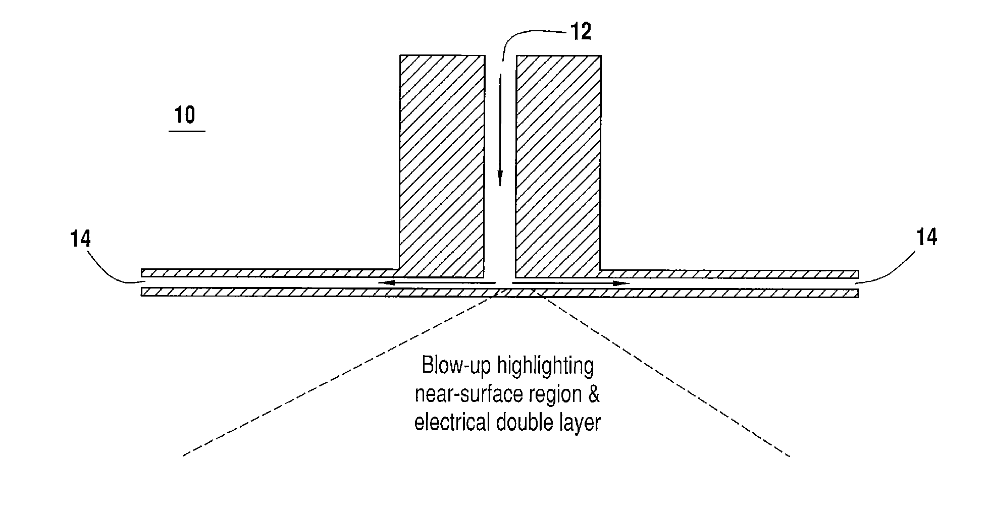
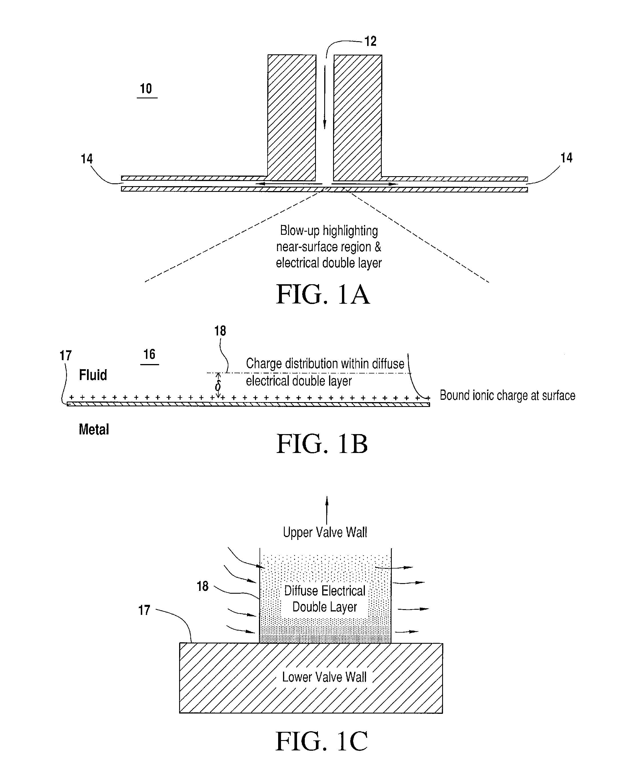
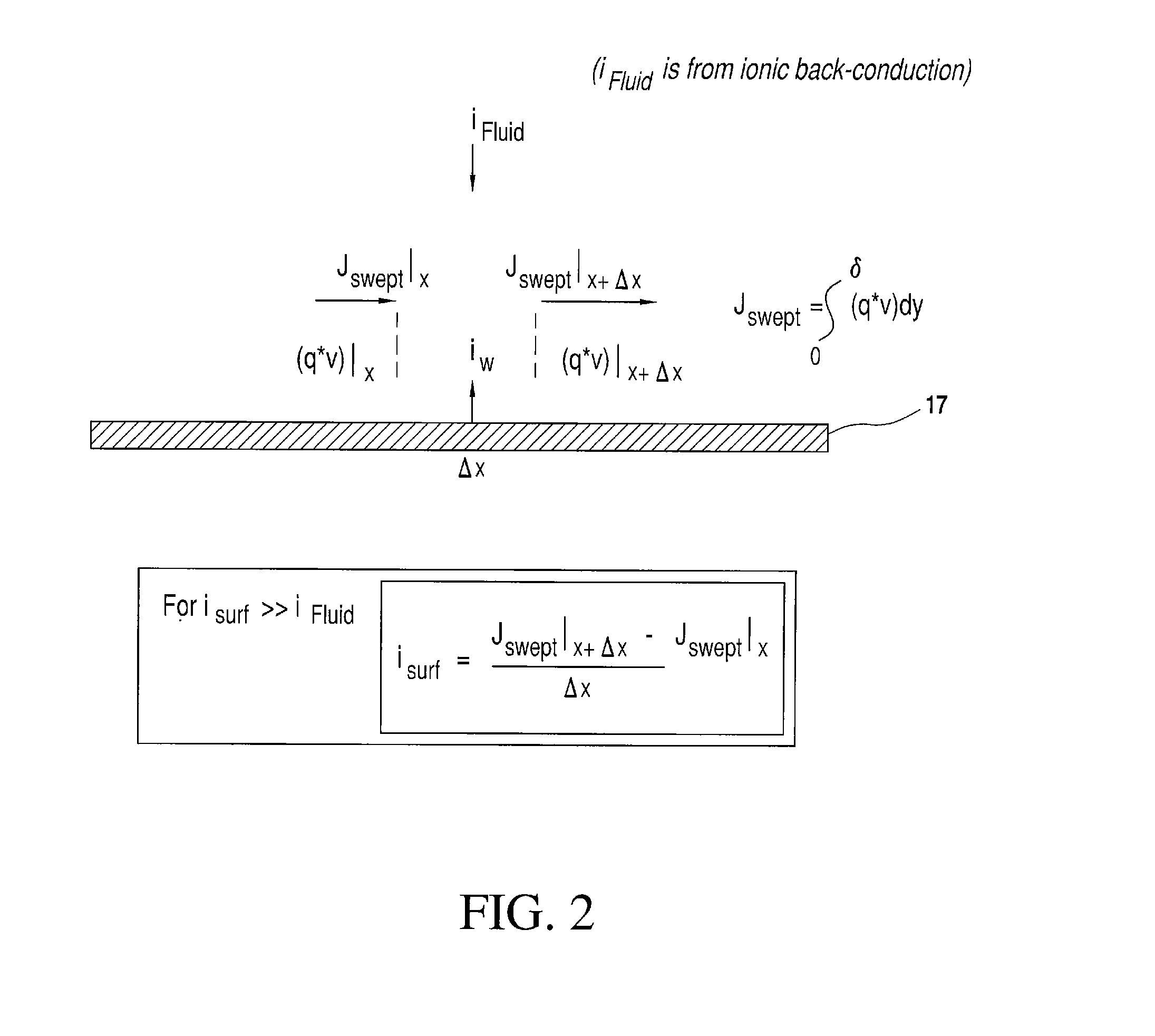
This corrosion is induced by the “sweeping of charge” in the electrical double layer that extends from the valve surface into the hydraulic fluid, resulting in electrochemical current driven between the valve and fluid.
Replacement of the hydrocarbon-based hydraulic fluid with a phosphate-ester-based hydraulic fluid has therefore had the undesirable consequence of modifying the electrical double layer to produce larger electrochemical currents, and therefore more significant corrosion.
Therefore, as valve geometries become more constrained and hydraulic operating pressures increase in hydraulic systems, the commercially available phosphate-ester-based hydraulic fluids, even with their additives, are incapable of reducing the electrokinetically driven surface currents.

Method used


Image

  • Redox couple-based mitigation of fluid-flow-driven electrochemical surface degradation
  • Redox couple-based mitigation of fluid-flow-driven electrochemical surface degradation
  • Redox couple-based mitigation of fluid-flow-driven electrochemical surface degradation

Examples


example 1

[0074]Testing is run using fluids with and without a metallocene redox couple. The metallocene redox couple is added to the test hydraulic fluid at a concentration ranging from about 0.05% to about 0.4%, by weight of charged metallocene and from about 0.05% to about 0.4% by weight of neutral metallocene. Test hardware is partitioned into two separate test systems: A) the fluid without the metallocene redox couple; and B) the fluid with the metallocene redox couple. Each test system includes:[0075]1. Reservoir for holding hydraulic fluid[0076]2. Pump to pressurize fluid to typical service pressures[0077]3. Pressurized fluid flow path to the test piece[0078]4. Test pieces with internal flow geometry (especially spatial variation of fluid flow velocity) and materials of construction similar to the hydraulic valve being simulated[0079]5. Return flow path on low-pressure side of valve, returning the fluid to the reservoir

[0080]Each of the test systems supports simultaneous testing of mul...

example 2

[0082]According to a further Example, testing is run using fluids with and without a ferrocenium / ferrocene redox couple. Ferrocence (0.2 wt %) (CAS registry number 102-54-5, molecular formula C10H10Fe) and a Ferrocenium salt, more specifically, Ferrocenium hexafluorophosphate (0.2 wt %) (CAS registry number 11077-24-0, molecular formula C10H10F6FeP) is added to the test hydraulic fluid. Test hardware is partitioned into two separate test systems: A) fluid without ferrocenium / ferrocene redox couple, and B) fluid with the ferrocenium / ferrocene redox couple. Each test system includes:[0083]1. Reservoir for holding hydraulic fluid[0084]2. Pump to pressurize fluid to typical service pressures[0085]3. Pressurized fluid flow path to the test piece[0086]4. Test pieces with internal flow geometry (especially spatial variation of fluid flow velocity) and materials of construction similar to the hydraulic valve being simulated[0087]5. Return flow path on low-pressure side of valve, returning t...


PUM

PropertyMeasurementUnit
oxidation currentsaaaaaaaaaa
reduction currentsaaaaaaaaaa
erosionaaaaaaaaaa

Abstract

The present disclosure relates to methods, systems, hydraulic fluids and additives for reducing the rate of surface current degradation for components in a hydraulic system, wherein the hydraulic system is exposed to phosphate-ester-based hydraulic fluid.

Description

TECHNOLOGICAL FIELD[0001]The present disclosure relates generally to the field of hydraulic systems. More specifically, the present invention relates to methods and additives for mitigating electrokinetically driven processes that occur in hydraulic systems.BACKGROUND[0002]As the aerospace industry transitioned from hydrocarbon-based hydraulic fluids to phosphate-ester-based hydraulic fluids it became apparent that hydraulic components (e.g. valves) that had operated reliably using the hydrocarbon-based hydraulic fluids were degrading prematurely during operation. It is believed that the use of phosphate-ester-based fluids may contribute to the erosion of the valve components, leading to unacceptable valve performance (e.g. leaking valves). An analysis of the factors causing valve failure in hydraulic systems revealed that electrokinetically driven corrosion is a significant contributing factor. This corrosion is induced by the “sweeping of charge” in the electrical double layer tha...

Claims


Application Information

Patent Timeline
Patent Type & Authority Applications(United States)
IPC IPC(8): C10M139/06C10M105/74C10M169/04
CPCC10M139/06C10M105/74C10M169/04F15B21/04C10N2010/14C10N2010/16C10M2223/0405C10M2223/0415C10M2227/081C10N2030/12C10N2040/13C10N2040/08C09K15/32C10N2010/12C10N2010/10
Inventor HAGER, HAROLD E
Owner THE BOEING CO
Why Eureka
Try Eureka