Area Monitoring Sensor

a monitoring sensor and area technology, applied in the direction of burglar alarm short radiation actuation, instruments, signalling systems, etc., can solve problems such as approving the hazard source, achieve the effects of reducing the interference between the measurement units, improving the detection accuracy of intruder objects, and simplifying the configuration of display units

Active Publication Date: 2016-06-02
KEYENCE
View PDF4 Cites 12 Cited by
  • Summary
  • Abstract
  • Description
  • Claims
  • Application Information

AI Technical Summary

Benefits of technology

[0019]In addition to the above configurations, in an area monitoring sensor according to still another embodiment of the invention, the measurement unit includes a light emission timing adjusting section for generating a timing control signal for adjusting light emission timing for each of the light projecting sections among a plurality of measurement units, and a control signal transmitting section for transmitting the timing control signal to the measurement unit that is connected through the input-output port. With such a configuration, mutual interference between the measurement units is reduced, thus allowing improvement in detection accuracy of the intruding object.
[0020]In addition to the above configurations, in an area monitoring sensor according to still another embodiment of the invention, the measurement unit further includes a power circuit that is connected with an external power supply to supply electric power to the display unit by use of electric power supplied from the external power supply. With such a configuration, the power circuit needs not be provided in the display unit, and hence a configuration of the display unit can be simplified.
[0021]According to the present invention, it is possible to provide the area monitoring sensor, the operating state of which a user can be checked without approaching the hazard source. Further, according to the present invention, it is possible to provide the area monitoring sensor which can be connected with the setting data creating device without approaching the hazard source.

Problems solved by technology

Thus, at the time of occurrence of abnormality such as detection of the intruding object, there is a problem of having to approach the hazard source so as to look at display contents of the display part for checking the operating state of the area monitoring sensor.
Further, also at the time of connection of the terminal device to the area monitoring sensor, there is a problem of having to approach the hazard source.

Method used


Image

  • Area Monitoring Sensor
  • Area Monitoring Sensor
  • Area Monitoring Sensor

Examples


first embodiment

1>

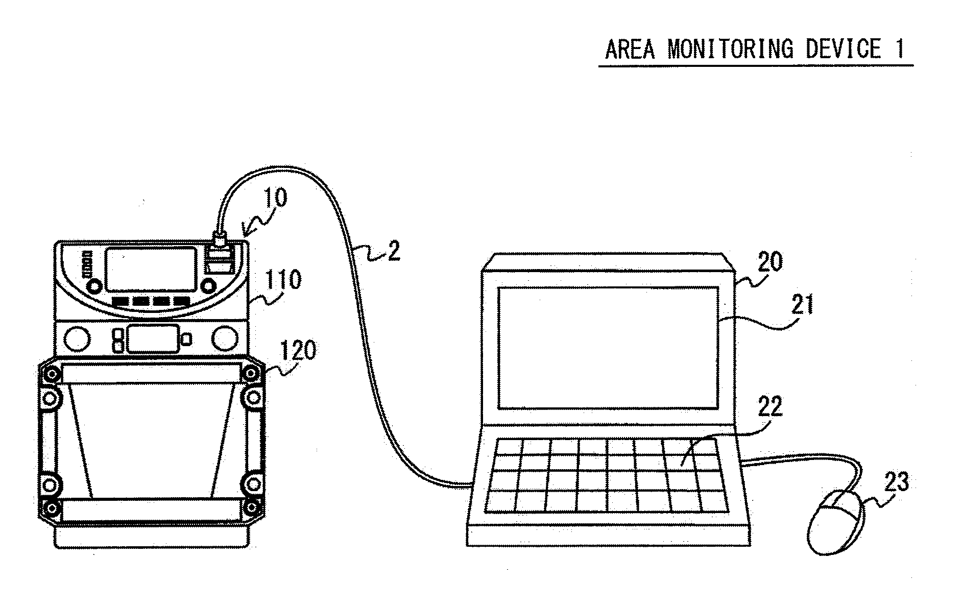
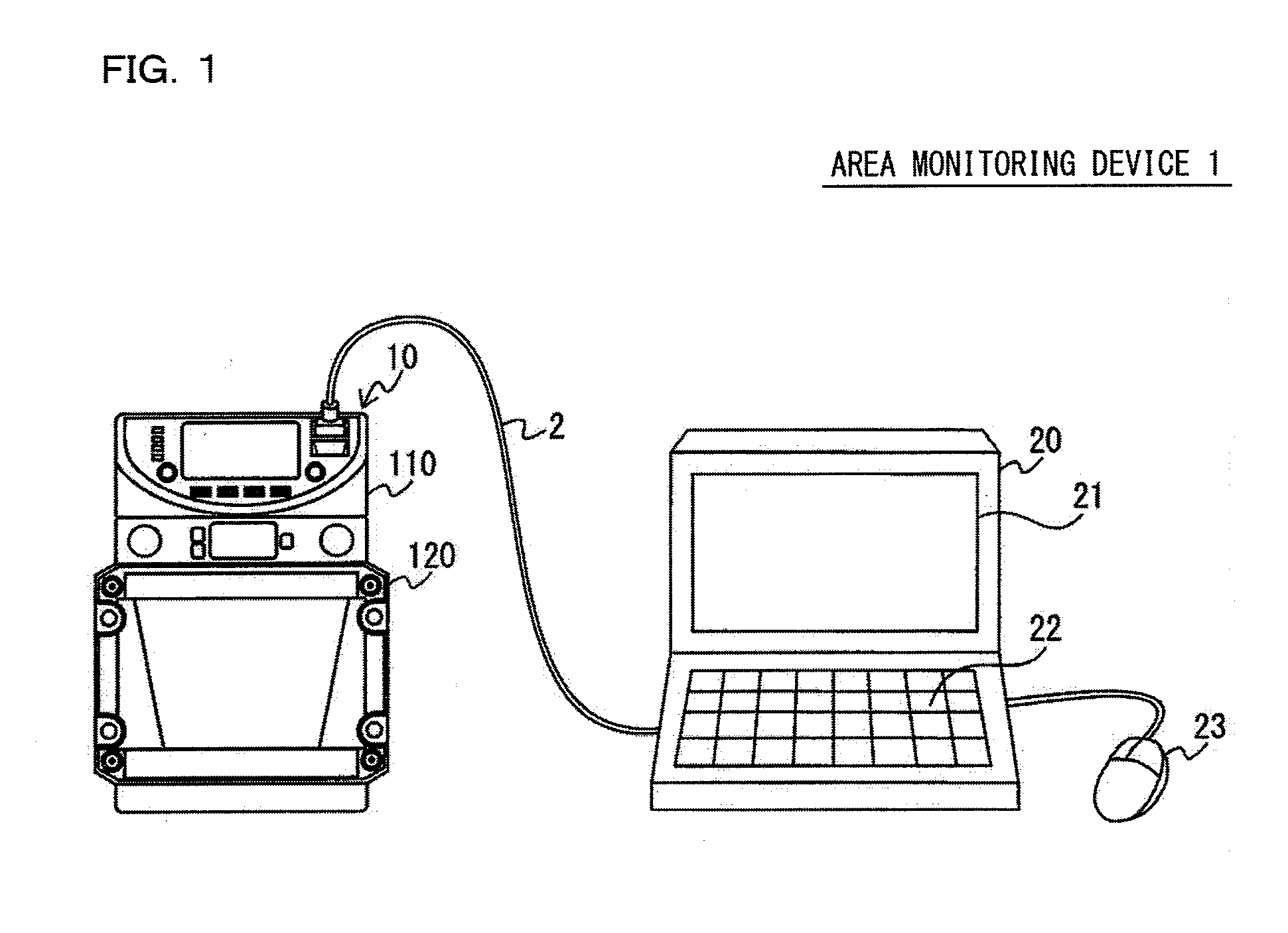
[0033]FIG. 1 is a perspective view showing one configuration example of an area monitoring device 1 including an area monitoring sensor 10 according to a first embodiment of the present invention. The figure shows the area monitoring sensor 10 capable of separating a display unit 110 from a measurement unit 120.

[0034]The area monitoring device 1 is configured of the area monitoring sensor 10 that detects an intruding object in a monitoring area to generate a stop signal for stopping an operation of an external device, and a setting data creating device 20 that creates setting data for the area monitoring sensor. The area monitoring sensor 10 and the setting data creating device 20 are connected through a communication cable 2.

[0035]The setting data creating device 20 is a terminal device such as a personal computer, which is provided with a screen display part 21, a key board 22 and a mouse 23, and installed with an application program for the area monitoring sensor. The setting d...

second embodiment

[0081]In the first embodiment, the description has been given of the example of the case where the display unit 110 and the measurement unit 120 are connected through the wiring cable 5. In contrast, in the present embodiment, a description will be given of a case where two or more measurement units 120 are connected to one display unit 110 through common buses.

[0082]FIG. 8 is an explanatory view schematically showing one example of a usage form of the area monitoring sensor 10 according to a second embodiment of the present invention. This figure shows two measurement units 120 each arranged in the vicinity of a wall B1 having steps. A first measurement unit 120 is arranged with its rear surface facing the wall surface, and a scan is performed with detection light in the circumferential direction about the measurement unit 120, to monitor a predetermined region.

[0083]However, with the wall B1 having the steps, a region B2, where the distance measurement cannot be performed by the f...


PUM


Abstract

There is provided an area monitoring sensor, an operating state of which a user can be checked without approaching a hazard source. An area monitoring sensor, which detects an intruding object in a monitoring area to generate a stop signal for stopping an operation of an external device, is configured of a measurement unit; a display unit that includes a screen display part for displaying an operating state of the measurement unit on a screen; and a wiring cable for detachably connecting the measurement unit and the display unit, to supply electric power between the measurement unit and the display unit.

Description

CROSS-REFERENCE TO RELATED APPLICATIONS[0001]The present application claims foreign priority based on Japanese Patent Application No. 2014-242906, filed Dec. 1, 2014, the contents of which is incorporated herein by reference.BACKGROUND OF THE INVENTION[0002]1. Field of the Invention[0003]The present invention relates to an area monitoring sensor, and more specifically relates to improvement in an area monitoring sensor that detects an intruding object in a monitoring area to generate a stop signal for stopping an operation of an external device.[0004]2. Description of Related Art[0005]An area monitoring sensor is a safety device which detects an intruding object, such as a person, that has intruded into a monitoring area, to generate a stop signal for stopping an operation of an external device such as a machine tool (e.g., Unexamined Japanese Patent Publication Nos. 2009-276173, 2009-276164, and 2009-282640).[0006]For example, the area monitoring sensor is provided with a light pro...

Claims


Application Information

Patent Timeline
Patent Type & Authority Applications(United States)
IPC IPC(8): G08B13/187G08B5/36
CPCG08B5/36G08B13/187F16P3/142F16P3/144G01V8/10G01V8/20G08B13/183
Inventor KAWANAKA, MASASHITAGASHIRA, TSUYOSHI
Owner KEYENCE
Why Eureka
Try Eureka