
Multi-panel antenna system

a multi-panel antenna and antenna system technology, applied in the direction of antennas, antenna details, collapsible antenna means, etc., can solve the problems of large shipping costs and consume valuable storage space in a warehouse, and achieve the effect of convenient adjustment of altitud

Active Publication Date: 2016-06-02
UBIQUITI INC
View PDF36 Cites 13 Cited by
  • Summary
  • Abstract
  • Description
  • Claims
  • Application Information

AI Technical Summary

Benefits of technology

The patent text describes a mounting assembly for a parabolic reflector that allows for easy adjustment of its direction. The assembly includes multiple reflector panels that can be aligned and secured together using inter-panel fasteners that prevent uncoubing. The assembly also includes a feed assembly and a multi-panel fastener that can securely attach the feed assembly to the reflector panels. The mounting assembly provides flexibility in adjusting the altitude and azimuth of the reflector's direction, making it ideal for applications such as weather monitoring or solar energy concentration.

Problems solved by technology

Unfortunately, any unused space in the antenna packaging may result in consuming valuable storage space in a warehouse.
To make matters worse, the large packaging dimensions can result in large shipping costs when the directional antenna is to be shipped to a reseller or to a customer.

Method used


Image

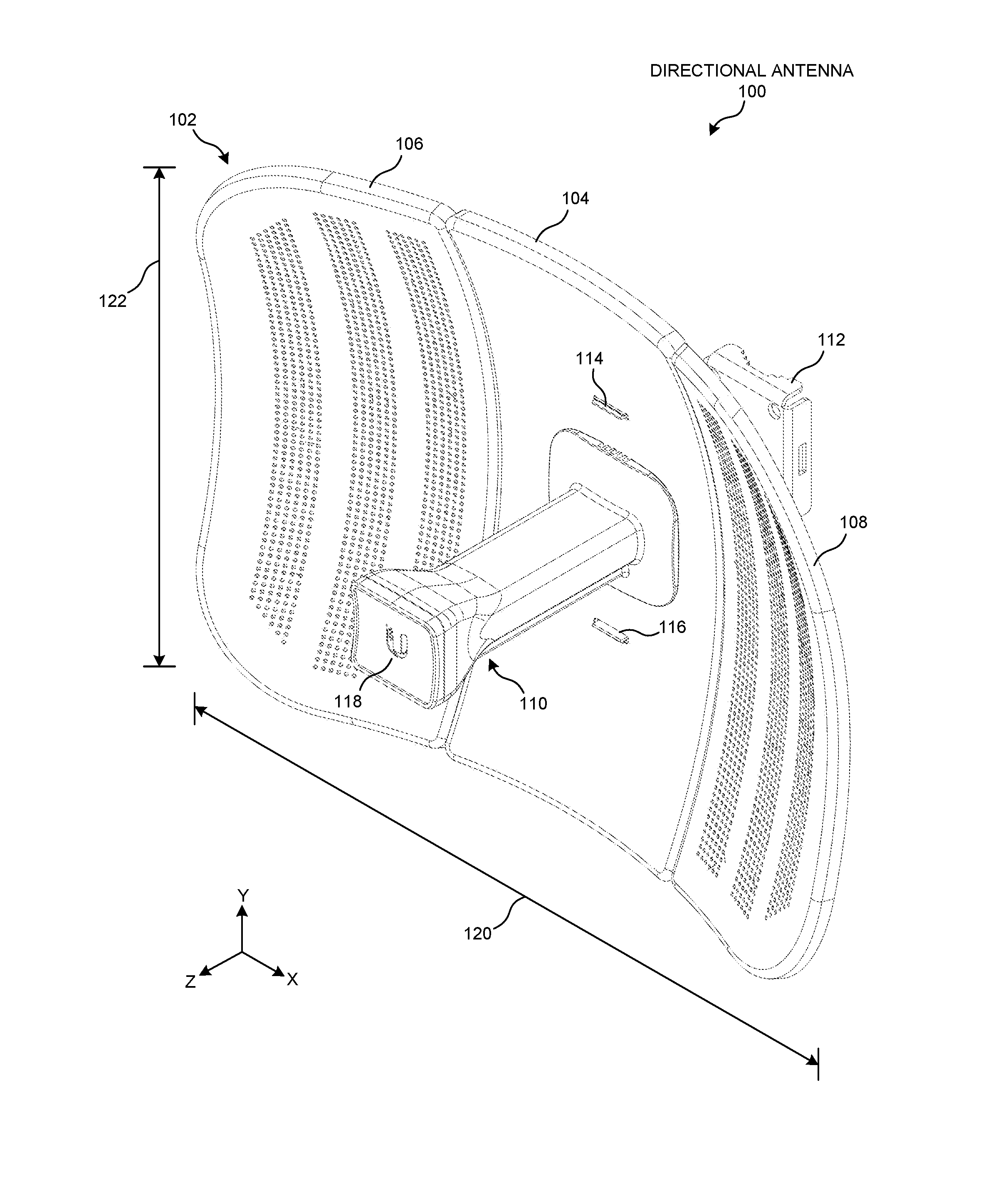
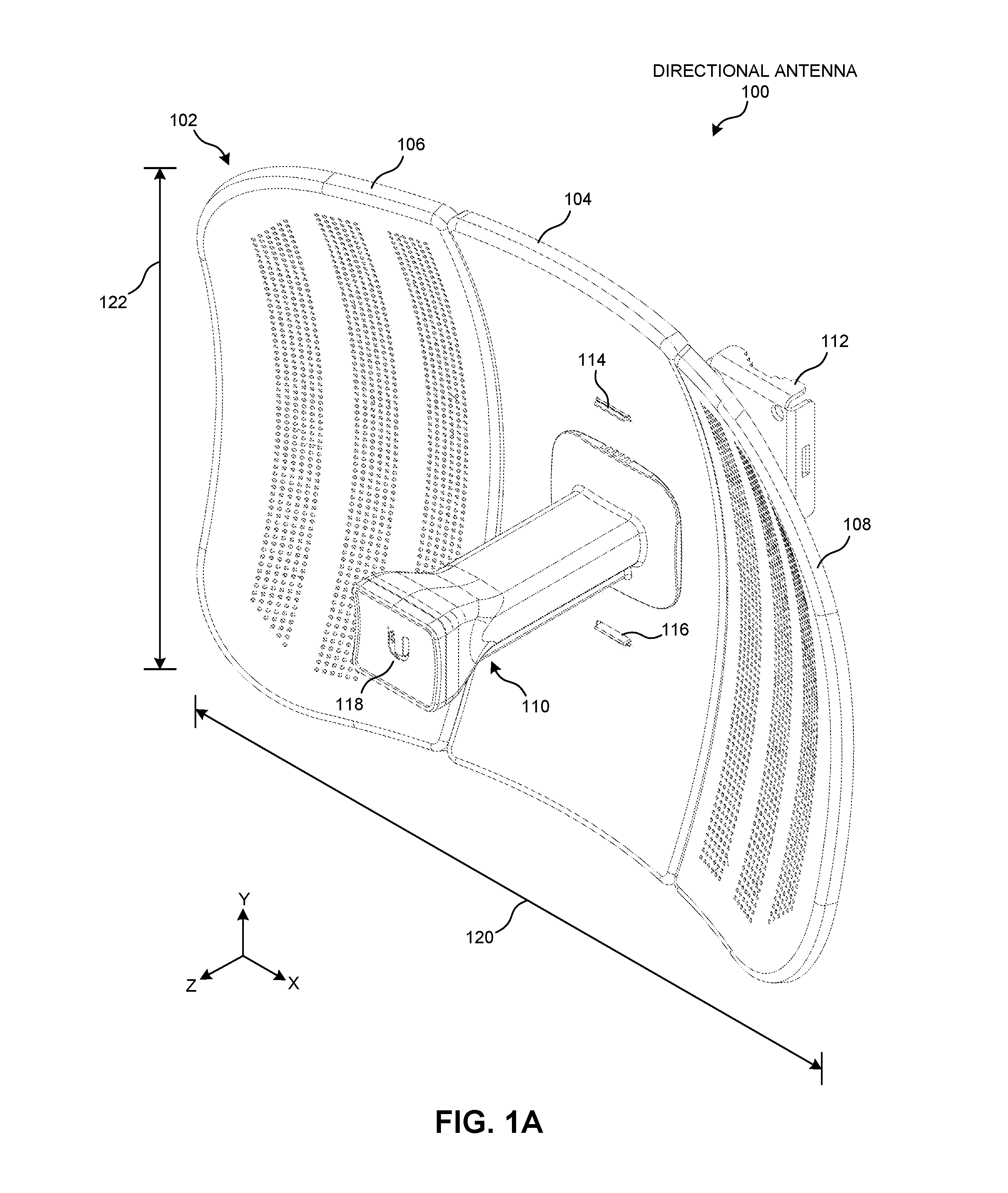
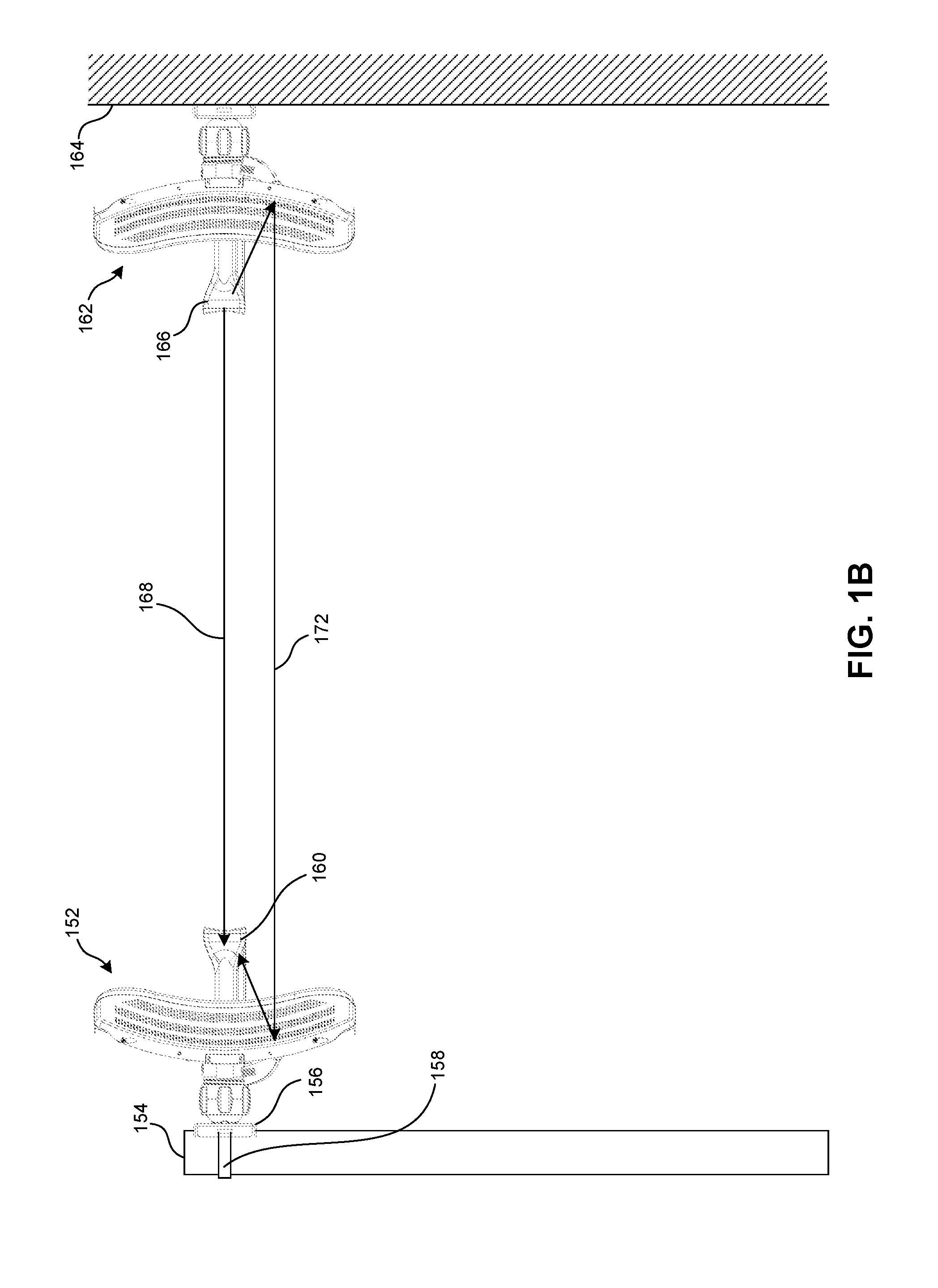
  • Multi-panel antenna system
  • Multi-panel antenna system
  • Multi-panel antenna system

Examples


Embodiment Construction

[0076]The following description is presented to enable any person skilled in the art to make and use the embodiments, and is provided in the context of a particular application and its requirements. Various modifications to the disclosed embodiments will be readily apparent to those skilled in the art, and the general principles defined herein may be applied to other embodiments and applications without departing from the spirit and scope of the present disclosure. Thus, the present invention is not limited to the embodiments shown, but is to be accorded the widest scope consistent with the principles and features disclosed herein.

Overview

[0077]Embodiments of the present invention solve the problem of packaging a kit for a directional antenna in a compact container. The kit can include multiple near-equal size panels that can be assembled into a multi-panel parabolic reflector, and can include an antenna feed assembly and mounting assembly that may be easy to fasten against the para...


PUM


Abstract

A multi-panel antenna system may be disassembled and packaged into a container with substantially smaller dimensions than the assembled antenna system. The antenna system may include two or more reflector panels, such that a respective reflector panel can include a curved surface that may form a portion of a parabolic reflector, and can include an inter-panel fastener operable to align a side surface of the respective reflector panel with a side surface of another reflector panel. The antenna system may also include a mounting assembly that may be used to fasten a convex side of the two or more reflector panels to a surface external to the antenna system, and a feed assembly that may be attached to the mounting assembly.

Description

RELATED APPLICATION[0001]This application is a continuation application of application Ser. No. 14 / 886,744, Attorney Docket Number UBNT15-1003NP, entitled “MULTI-PANEL ANTENNA SYSTEM,” by inventor Jude Lee, filed 19 Oct. 2015, which claims the benefit of:[0002]U.S. Provisional Application No. 62 / 086,525, entitled “Multiple Panel Parabolic Reflector Dish Antennas,” by inventor Jude Lee, filed Dec. 2, 2014; and[0003]U.S. Provisional Application No. 62 / 191,232, Attorney Docket Number UBNT15-1003PSP, entitled “MULTI-PANEL ANTENNA SYSTEM,” by inventor Jude Lee, filed 10 Jul. 2015,the disclosures of which are incorporated herein in their entirety.BACKGROUND[0004]1. Field[0005]This disclosure is generally related to a multi-panel directional antenna. More specifically, this disclosure is related to a directional antenna that can be transported in a compact package, and is easily assembled by an end-user.[0006]2. Related Art[0007]Directional antennas typically include a wide parabolic refle...

Claims


Application Information

Patent Timeline
IPC IPC(8): H01Q15/16H01Q15/14H01Q1/24
CPCH01Q15/162H01Q15/141H01Q1/24H01Q1/12H01Q15/14H01Q1/088H01Q1/1207H01Q1/125H01Q19/12H01Q3/08H01Q1/1264
Inventor LEE, JUDE
Owner UBIQUITI INC
Learn More