Attachment structure for binding band

a technology of attachment structure and binding band, which is applied in the direction of hose connection, mechanical apparatus, transportation and packaging, etc., can solve the problems of increasing production cost, cumbersome and time-consuming, and complicating the structure of the holding body, so as to improve productivity, simplify the structure, and reduce the effect of cos

Inactive Publication Date: 2016-06-09
SUMITOMO WIRING SYST LTD
View PDF6 Cites 0 Cited by
  • Summary
  • Abstract
  • Description
  • Claims
  • Application Information

AI Technical Summary

Benefits of technology

[0010]According to this aspect, a locking portion of the binding band to the holding body can be formed by a simple structure of providing the recess open on the supporting wall and the side wall of the holding body and providing the locking projection in such a recess. Thus, it is possible to simplify the structure, improve productivity and reduce cost as compared with a structure of providing a guide wall in the supporting wall of the holding body like a conventional structure.
[0011]Further, the locking projection to which the binding band is locked is exposed to outside through the opening of the recess. Accordingly, the visibility of the locking projection is ensured and access is facilitated. Thus, the binding band can be locked reliably and quickly to the locking projection and attachment operability can be improved as compared with the case where the binding band is inserted into two insertion holes provided on the supporting wall of the holding body in a state where visual confirmation is not possible as in the conventional structure.
[0012]In addition, the locking projection to which the binding band is locked projects in the recess open on the supporting wall and the side wall. Thus, the band main body curved in advance to have an opening width of the recess can be inserted through the side wall opening and locked to the locking projection with the binding band arranged in a ring-like manner around the held body. Thus, it is not necessary to ensure a large space for curving the binding band and it is possible to provide the attachment structure for binding band also in a narrow area. By binding the binding band locked to the locking projection in this way together with the held body, the held body easily is attached fixedly to the holding body with good operability and space efficiency by the binding band.
[0013]A retaining protrusion may be provided on a projecting tip part of the locking projection. Accordingly, disengagement of the binding band from the locking projection is prevented by the interference of the binding band with the retaining protrusion even if the binding band is displaced to a tip side of the locking projection due to vehicle vibration or the like. Thus, the separation of the held body from the holding body is prevented.
[0014]The side wall may include a first side wall portion and a second side wall portion extending in directions different from each other, and the recess is open on both the first and second side walls. Accordingly, the visibility and accessibility of the locking projection are further improved and an operation of locking the binding band to the locking projection can be performed more quickly and reliably.
[0015]According to the present invention, the locking portion of the binding band to the holding body can be formed by the simple structure of providing the recess open on the supporting wall and the side wall of the holding body and providing the locking projection in such a recess. Thus, it is possible to simplify the structure, improve productivity and reduce cost as compared with a structure of providing a guide wall like the conventional structure. Further, since the locking projection to which the binding band is locked is exposed to outside through the opening of the recess, the visibility of the locking projection is ensured and access is facilitated. In addition, the band main body can be inserted through the side wall opening and locked to the locking projection with the binding band arranged in a ring-like manner around the held body. Thus, the attachment structure for binding band can be provided also in a narrow area.

Problems solved by technology

However, an operation of pulling out the tip part of the binding band inserted into one of the two insertion holes provided on the supporting wall portion of the holding body from the other had problems of requiring the tip part of the binding band to be curved in a desired direction, being very cumbersome and taking time.
However, it has caused problems of complicating the structure of the holding body and increasing production cost to provide such a guide wall on a back side of the supporting wall portion of the holding body.
Thus, in either case, the enlargement of the attachment structure is unavoidable.
If a large space cannot be secured in the holding body, the guide wall cannot be provided and, hence, there has been still room for improvement.

Method used


Image

  • Attachment structure for binding band
  • Attachment structure for binding band
  • Attachment structure for binding band

Examples


Embodiment Construction

[0020]Hereinafter, embodiments of the present invention are described with reference to the drawings.

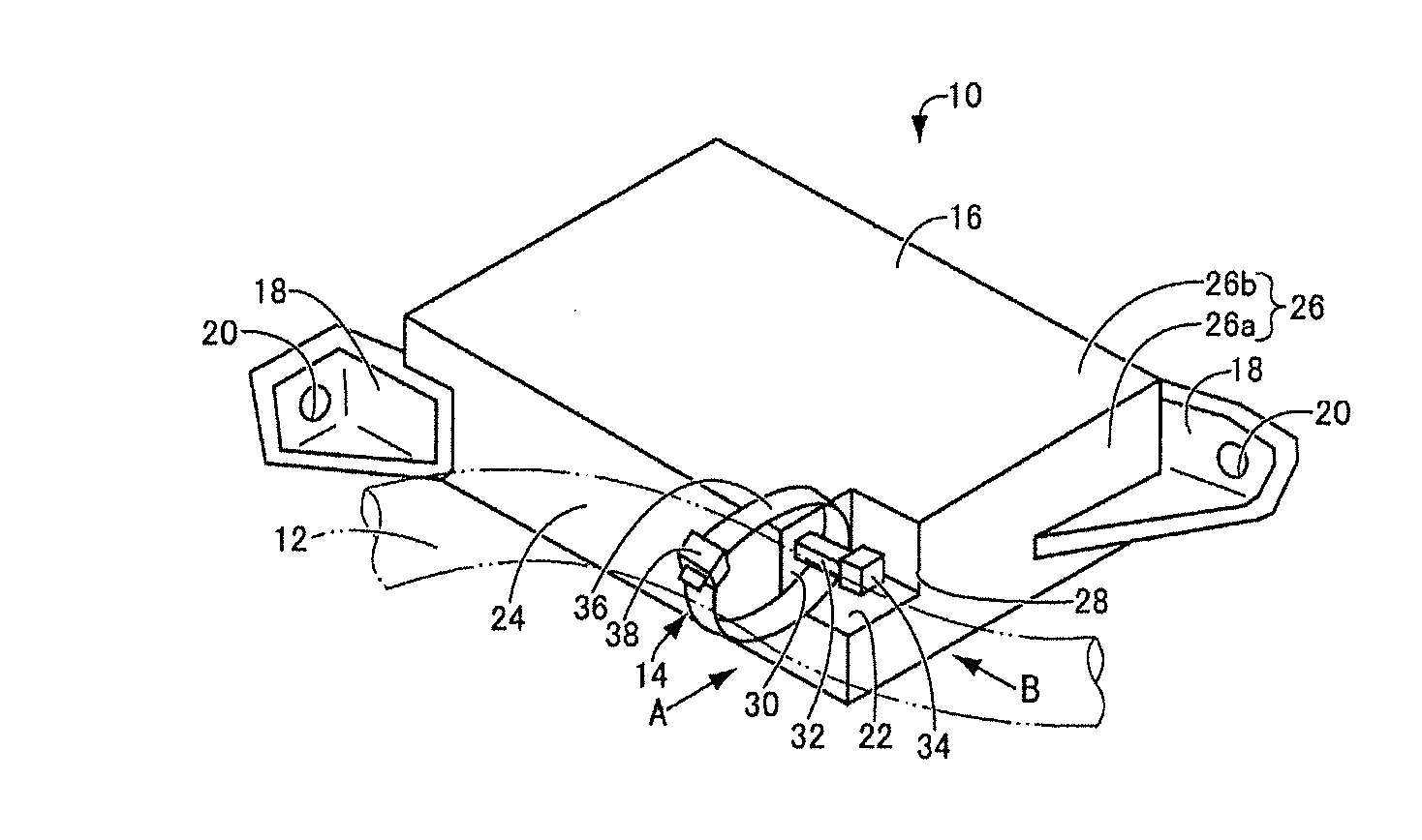
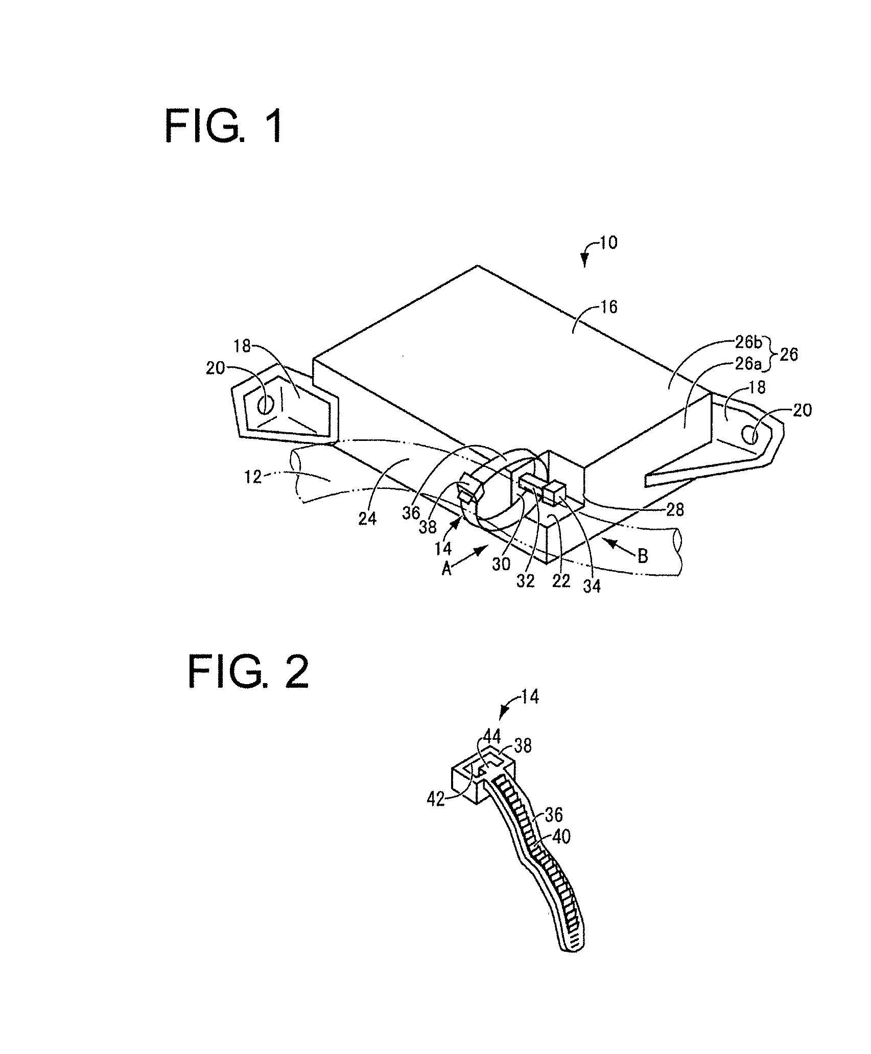
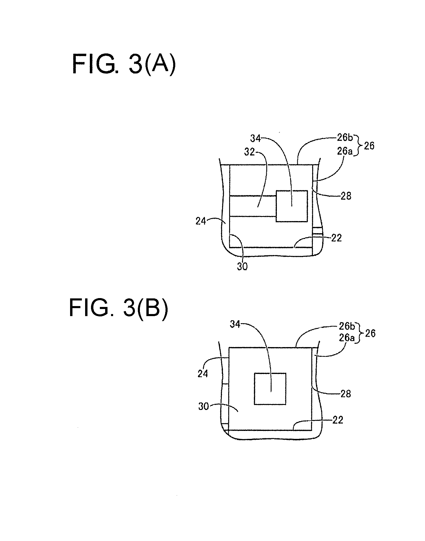
[0021]FIGS. 1 to 3 show a structure for binding and fixing a wiring harness 12 as a held body to a later-described supporting wall portion 24 of an electrical connection box 10 as a holding body by a binding band 14 using an attachment structure for binding band as one embodiment of the present invention. As shown in FIG. 1, the electrical connection box 10 is configured so that unillustrated various electrical components, busbars, connectors, etc. are arranged in a case 16 having a substantially block shape. Attachment leg portions 18 are formed to extend outward from two positions on the outer surface of this case 16 and fixed to a vehicle or the like by mounting unillustrated fixing bolts into bolt insertion holes 20 penetrating through the attachment leg portions 18. Here, the case 16 and the attachment leg portions 18 are formed integrally or unitarily of synthetic resin such as...


PUM


Abstract

An attachment structure for binding band is for binding and fixing a held body (12) to a supporting wall (24) of a holding body (10) by a binding band (14) and includes a recess (22) open on the supporting wall (24) of the holding body (10) and a side wall (26) intersecting with the supporting wall (24) and a locking projection (32) cantilevered toward a side wall opening (28) of the recess (22) from a bottom surface (30) facing the side wall portion opening (28). The binding band (14) is tightened together with the held body (12) in a state where a band main body (36) of the binding band (14) arranged in a ring-like manner around the held body (12) is inserted into the recess (22) through the side wall opening (28) and locked to the locking projection (32).

Description

BACKGROUND[0001]1. Field of the Invention[0002]The present invention relates to an attachment structure for binding band for binding and fixing a held body to a holding body by a binding band.[0003]2. Description of the Related Art[0004]Conventionally, in attaching a held body such as a wiring harness to be routed in an automotive vehicle to a holding body such as an electrical connection box or a bracket, an attachment structure for binding and fixing the held body to a supporting wall portion of the holding body by a binding band has been widely adopted. Such an attachment structure for binding band is, for example, known from Japanese Unexamined Patent Publication No. 2008-232222. Specifically, two insertion holes are provided on a supporting wall portion of an electrical connection box as a holding body, a binding band is locked to the supporting wall portion of the holding body and the binding band is tightened together with a wiring harness as a held body by pulling out a tip ...

Claims


Application Information

Patent Timeline
Patent Type & Authority Applications(United States)
IPC IPC(8): B65D63/10
CPCB65D2563/101B65D63/1027F16B2/08H02G3/30B65D63/1063B60R16/0215
Inventor IWATA, MAKOTO
Owner SUMITOMO WIRING SYST LTD
Why Eureka
Try Eureka