
Devices and methods for thermally-mediated chemical reactions

a chemical reaction and apparatus technology, applied in the field of apparatus and methods for thermal cycling specimens, can solve the problems of requiring an intervening material, and requiring a large number of liquid volumes to be heated and cooled

Active Publication Date: 2016-06-09
LIFE TECH CORP
View PDF3 Cites 2 Cited by
  • Summary
  • Abstract
  • Description
  • Claims
  • Application Information

AI Technical Summary

Problems solved by technology

The primary limitation of this approach is the requirement for an intervening material between the energy source and the heated or cooled liquid.
Miniaturization and scaling to larger numbers of liquid volumes to be heated and cooled is particularly problematic with the current art because of the dual design constraints of having to seal and heat / cool a large volumes of liquids contained in the well of a thermoplastic microtiter well plate.

Method used


Image

  • Devices and methods for thermally-mediated chemical reactions
  • Devices and methods for thermally-mediated chemical reactions
  • Devices and methods for thermally-mediated chemical reactions

Examples


case 200

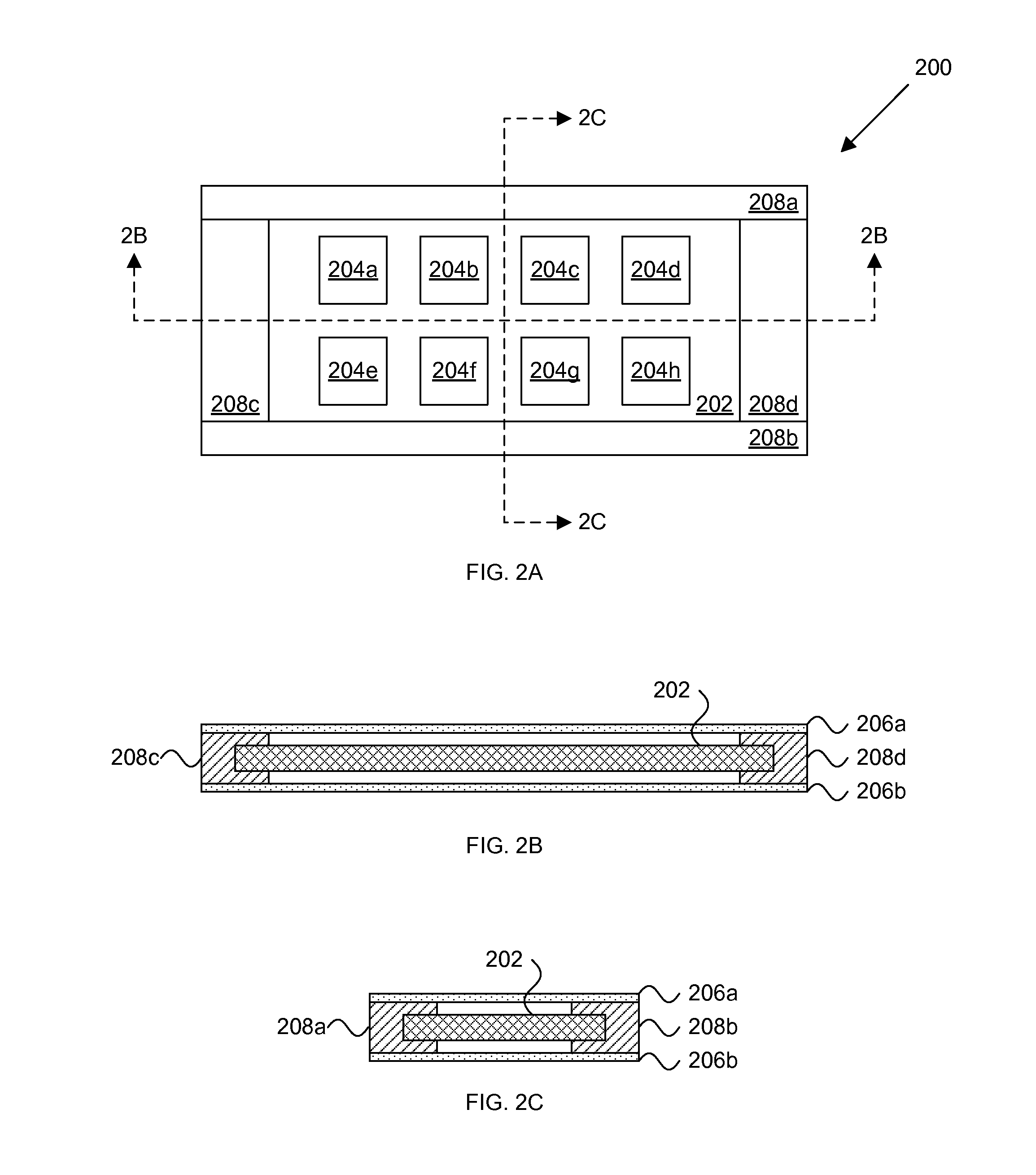
[0065]Case 200 can be formed from a variety of materials capable of holding through-hole array 202 and immiscible liquid (not depicted). In one embodiment, the case 200 is fabricated from two platens 206a, 206b connected by one or more gaskets 208a-208d. The platens can include a variety of materials such as glass, plastics, metals, and the like. In some embodiments, at least one of platens 206a, 206b are optically transparent to allow for monitoring of reactions in the through-hole array during thermal cycling or during isothermal amplification reactions. Additionally or alternatively, one of the platens 206a, 206b can be optically opaque and / or non-reflective to minimize unwanted reflections when imaging.

[0066]In various embodiments where the rapid heating and / or cooling of the through-hole array 202 is desired, thinner platens 206a, 206b can be used. Thermal conduction through glass scales in proportion to thickness. Accordingly, the use of microscope slide covers, which are abou...


PUM


Abstract

One aspect of the invention provides container for thermal cycling a plurality of samples in a microfluidic array. The container includes a plurality of walls defining an interior volume and a conductive member for heating the interior volume. Another aspect of the invention provides container for thermal cycling a plurality of samples in a microfluidic array. The container includes a plurality of walls defining an interior volume and a plurality of conductive members for heating an interior volume. Another aspect of the invention provides a container for thermal cycling a plurality of samples in a microfluidic array. The container includes a plurality of walls defining an interior volume and a first conductive member located in the interior volume and adapted to contact a first end of the microfluidic array.

Description

CROSS REFERENCES TO RELATED APPLICATIONS[0001]This application claims priority to U.S. Provisional Patent Application Ser. No. 61 / 034,321, filed Mar. 6, 2008. The contents of this patent application are hereby incorporated by reference in their entirety.TECHNICAL FIELD[0002]New apparatus and methods for thermal cycling specimens are provided herein. The methods are applicable to specimens held in a variety of laboratory vessels and are particularly advantageous when used in conjunction with specimens held in a through-hole array.BACKGROUND[0003]Various research and diagnostic techniques employ thermally-mediated chemical reactions such as the polymerase chain reaction (PCR), nucleic acid hybridization, and protein immunoassays and / or thermally-controlled environments for cell culture. Such techniques utilize a thermal cycler (also known as a thermocycler, PCR machine, and / or DNA amplifier). Thermal cyclers provide the high temperatures necessary to physically separate the strands of...

Claims


Application Information

Patent Timeline
Patent Type & Authority Applications(United States)
IPC IPC(8): C12Q1/68B01L3/00B01L7/00
CPCC12Q1/686B01L7/52B01L3/502715B01L2200/10B01L2300/1894B01L2300/0819B01L2300/0848B01L2300/12B01L2300/1822B01L2200/027B01L3/5027B01L3/50851B01L3/50857B01L2300/0877B01L2300/1827B01L2300/1833B01L2300/1844B01L2300/185
Inventor BRENAN, COLIN J.H.MORRISON, THOMAS B.KANIGAN, TANYA S.
Owner LIFE TECH CORP
Features
  • Generate Ideas
  • Intellectual Property
  • Life Sciences
  • Materials
  • Tech Scout
  • Unparalleled Data Quality
  • Higher Quality Content
  • 60% Fewer Hallucinations
Learn More