Antireflection film and organic light emitting device provided with the same

an anti-reflection film and light-emitting device technology, applied in the direction of instruments, polarising elements, optical elements, etc., can solve the problems of reducing display quality, deteriorating visibility, deteriorating visibility and contrast ratio, etc., to compensate the deterioration of visibility, strong viewing angle dependency, and strong viewing angle dependen

Active Publication Date: 2016-06-09
SAMSUNG ELECTRONICS CO LTD
View PDF1 Cites 1 Cited by
  • Summary
  • Abstract
  • Description
  • Claims
  • Application Information

AI Technical Summary

Benefits of technology

[0030]Since a conventionally-developed circular polarizing plate has strong viewing angle dependency, visibility may be deteriorated when viewed by an observer from the side. In order to compensate the deterioration in visibility, a compensation film may be laminated, but the lamination increases the entire thickness of the OLED and thus thinness is difficult to realize. In contrast, exemplary embodiments of an anti-reflection film improve display characteristics by decreasing viewing angle dependency without increasing the thickness of the film.

Problems solved by technology

However, the visibility and the contrast ratio may be deteriorated by reflection of exterior light, thereby reducing display quality.
Since a conventionally-developed circular polarizing plate has strong viewing angle dependency, visibility may be deteriorated when viewed by an observer from the side.
In order to compensate the deterioration in visibility, a compensation film may be laminated, but the lamination increases the entire thickness of the OLED and thus thinness is difficult to realize.

Method used


Image

  • Antireflection film and organic light emitting device provided with the same
  • Antireflection film and organic light emitting device provided with the same
  • Antireflection film and organic light emitting device provided with the same

Examples


example 1

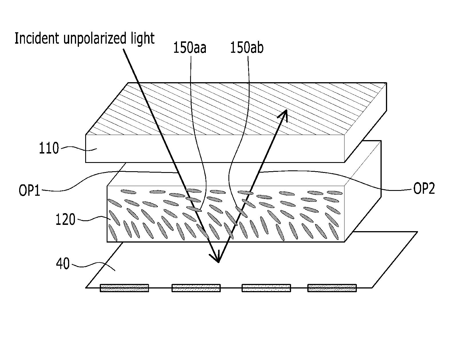
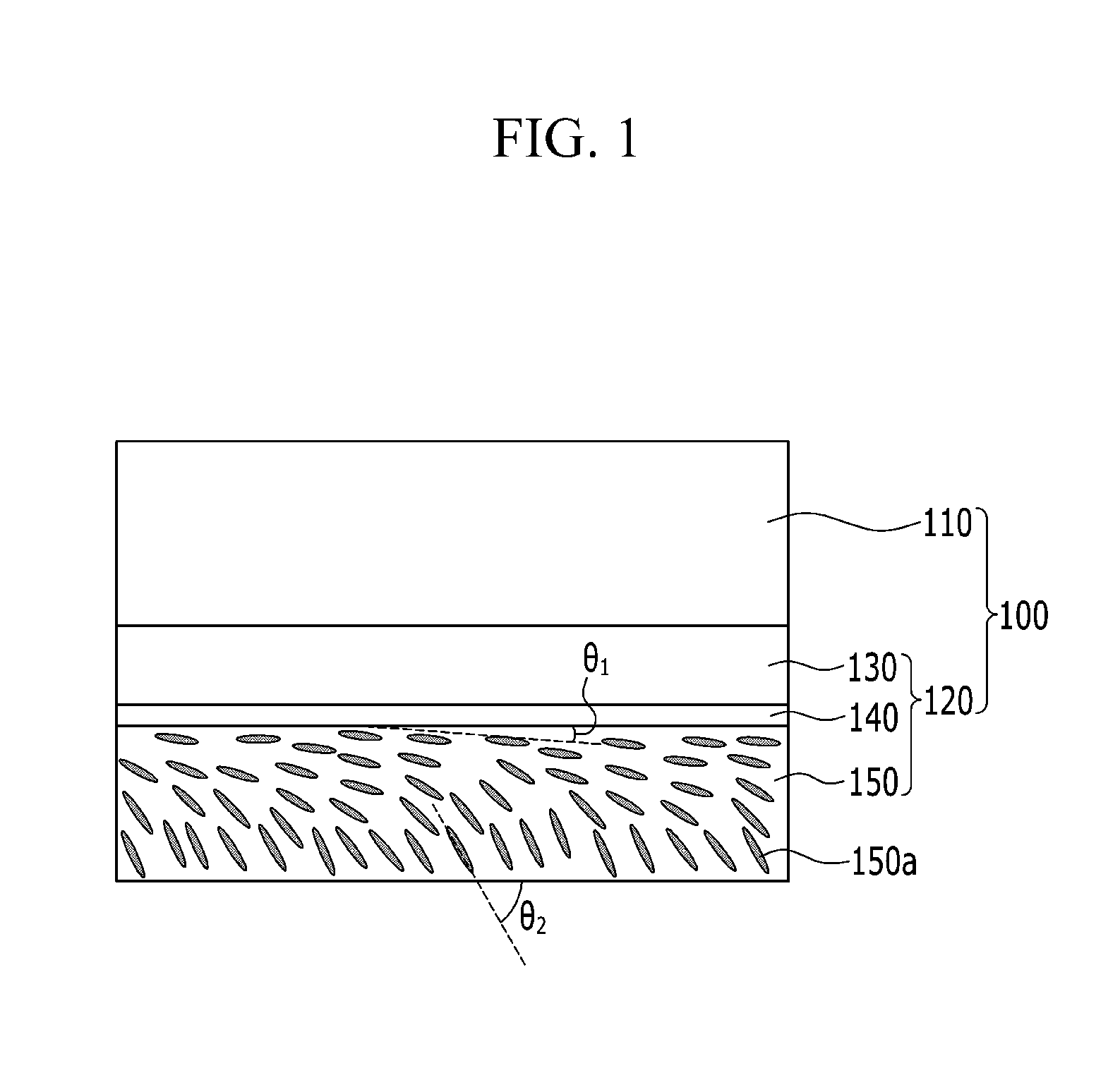
[0119]A simulation evaluation (LCD Master (Shintech Inc.)) is performed by simulation-setting of a structure formed by sequentially disposing a polarizer, a compensation film (Re=138 nm) including a liquid crystal layer, and a reflector. Herein, the liquid crystal layer of the compensation film has a bottom tilt structure (see FIG. 1) in which a tilt angle of the liquid crystals is larger from the top to the bottom. The minimum tilt angle (an upper tilt angle) is about 3° and the maximum tilt angle (a lower tilt angle) is about 37°, between which the tilt angle gradually changes. The wavelength dispersion (WD) of the liquid crystal layer (Re (450 nm) / Re (550 nm)) is 0.82. The angle of an axis of the polarizer is set at about 90° and the angle of an axis of the compensation film is set at about 45°.

example 2

[0120]A simulation condition is set according to the same method as Example 1, except the maximum tilt angle (the lower tilt angle) of the liquid crystals in the liquid crystal layer of the compensation film (Re=138 nm) is set at about 45°.

example 3

[0121]A simulation condition is set according to the same method as Example 1, except the maximum tilt angle (the lower tilt angle) of liquid crystals in the liquid crystal layer of the compensation film (Re=138 nm) is set at about 65°.


PUM

PropertyMeasurementUnit
tilt angleaaaaaaaaaa
wavelengthaaaaaaaaaa
anti-reflectionaaaaaaaaaa

Abstract

An organic light emitting device includes an anti-reflection film including a polarizer and a compensation film positioned on the polarizer and including a liquid crystal layer which includes liquid crystals oriented in a direction tilting obliquely with respect to a surface of the liquid crystal layer extending in a horizontal direction in a cross sectional view, tilt angles of the liquid crystals are gradually larger from the first side to the second side, a maximum tilt angle of the liquid crystals with respect to the surface of the liquid crystal layer is from about 15° to about 80°, and in-plane retardation (Re) of the liquid crystal layer for incident light of a 450 nm wavelength and a 550 nm wavelength satisfies a Relationship 1.

Description

CROSS-REFERENCE TO RELATED APPLICATION[0001]This application claims priority to Korean Patent Applications No. 10-2014-0174872 and 10-2015-0171754, filed on Dec. 8, 2014 and Dec. 3, 2015, respectively, and all the benefits accruing therefrom under 35 U.S.C. §119, the content of which in its entirety is herein incorporated by reference.BACKGROUND[0002]1. Field[0003]An anti-reflection film and an organic light emitting device including the same are disclosed.[0004]2. Description of the Related Art[0005]Recently, as demand for lightness and thinness of a display device such as a monitor, a television, or the like, has increased, an organic light emitting device (“OLED”) has drawn attention. The OLED is a self light-emitting display device, which does not need a separate backlight, and thus may realize a thin and flexible display device.[0006]The OLED may reflect external light by a metal electrode and a metal line of the organic light emitting display panel. However, the visibility and...

Claims


Application Information

Patent Timeline
Patent Type & Authority Applications(United States)
IPC IPC(8): G02B5/30H01L51/52G02F1/1337
CPCG02B5/3083G02B5/3016G02F2001/133761H01L51/5281G02F1/133753G02B1/111G02B5/305G02F1/13363H10K50/86H10K59/50
Inventor KAMADA, KOHOHYAMA, TSUYOSHILEE, EUN SUNGCHOI, HYUNSEOKLEE, SEUNGHYUN
Owner SAMSUNG ELECTRONICS CO LTD
Why Eureka
Try Eureka