Antireflection film and organic light emitting diode device including the same

an anti-reflection film and organic light technology, applied in non-linear optics, instruments, polarising elements, etc., can solve the problems of reducing display quality, deteriorating visibility, and deteriorating visibility toward a side, so as to reduce the reflection of exterior light, strong viewing angle dependency, and reduce the effect of deteriorating visibility

Active Publication Date: 2018-09-25
SAMSUNG ELECTRONICS CO LTD
View PDF53 Cites 1 Cited by
  • Summary
  • Abstract
  • Description
  • Claims
  • Application Information

AI Technical Summary

Benefits of technology

[0007]A conventional circular polarizing plate typically has strong viewing angle dependency, such that visibility may be deteriorated toward a side when such conventional circular polarizing plate is applied to an organic light emitting diode device to reduce reflection of exterior light.
[0008]Embodiments provide an antireflection film having improved display characteristics with reduced viewing angle dependency:

Problems solved by technology

In the organic light emitting device, external light may be reflected by a metal electrode and a metal line of the organic light emitting display panel, and the visibility and the contrast ratio may be deteriorated by reflection of the exterior light, thereby reducing display quality.
A conventional circular polarizing plate typically has strong viewing angle dependency, such that visibility may be deteriorated toward a side when such conventional circular polarizing plate is applied to an organic light emitting diode device to reduce reflection of exterior light.

Method used


Image

  • Antireflection film and organic light emitting diode device including the same
  • Antireflection film and organic light emitting diode device including the same
  • Antireflection film and organic light emitting diode device including the same

Examples


example 1

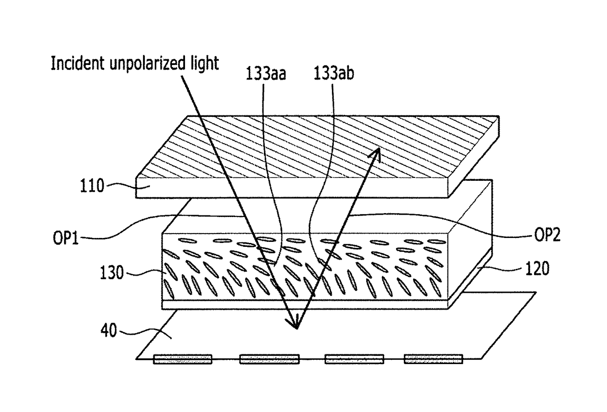
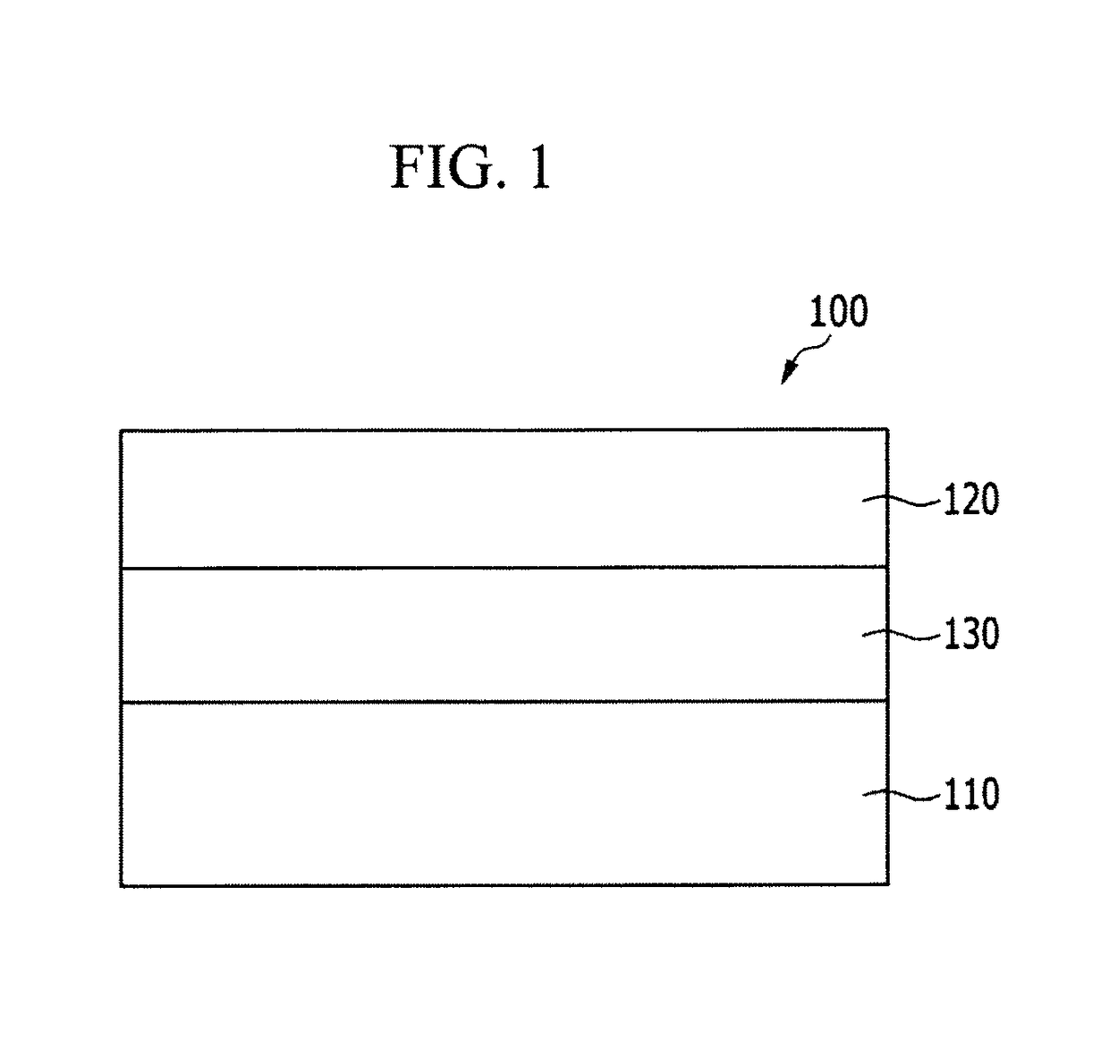
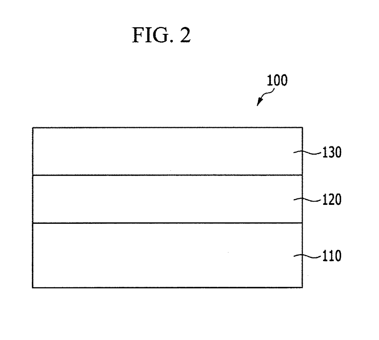
[0136]For a simulation evaluation, a polarizer, a λ / 4 phase delay layer (Re2=138 nm), a λ / 2 phase delay layer (Re1=275 nm), and a reflector are sequentially disposed, e.g., stacked, one on another. Herein, the λ / 4 phase delay layer includes a liquid crystal layer including a plurality of liquid crystals having a tilt angle that is gradually changed between a lower tilt angle (a minimum tilt angle) of 3° and an upper tilt angle (a maximum tilt angle) of 60°. The polarizer is disposed to have an axis angle of 90°, the λ / 2 phase delay layer is disposed at 75°, and the λ / 4 phase delay layer is disposed at 15°.

example 2

[0137]For a simulation evaluation, a polarizer, a λ / 4 phase delay layer (Re2=124 nm), a λ / 2 phase delay layer (Re1=248 nm), and a reflector are sequentially disposed, e.g., stacked, one on another. Herein, the λ / 4 phase delay layer includes a liquid crystal layer including a plurality of liquid crystals having a tilt angle that is gradually changed between a lower tilt angle (a minimum tilt angle) of 3° and an upper tilt angle (a maximum tilt angle) of 60°. The polarizer is disposed to have an axis angle of 90°, the λ / 2 phase delay layer is disposed at 75°, and the λ / 4 phase delay layer is disposed at 15°.

example 3

[0138]For a simulation evaluation, a polarizer, a λ / 4 phase delay layer (Re2=124 nm), a λ / 2 phase delay layer (Re1=248 nm), and a reflector are sequentially disposed, e.g., stacked, one on another. Herein, the λ / 4 phase delay layer is configured to include a liquid crystal layer including a plurality of liquid crystals having a tilt angle that is gradually changed between a lower tilt angle (a minimum tilt angle) of 3° and an upper tilt angle (a maximum tilt angle) of 45°. The polarizer is disposed to have an axis angle of 90°, the λ / 2 phase delay layer is disposed at 75°, and the λ / 4 phase delay layer is disposed at 15°.


PUM

PropertyMeasurementUnit
wavelengthsaaaaaaaaaa

Abstract

An antireflection film includes a polarizer, a first phase delay layer, and a second phase delay layer, where at least one of the first phase delay layer and the second phase delay layer includes a liquid crystal layer, and the liquid crystal layer includes liquid crystals oriented in a direction tilting obliquely with respect to a surface thereof.

Description

CROSS-REFERENCE TO RELATED APPLICATIONS[0001]This application claims priority to Korean Patent Application No. 10-2014-0190805 filed on Dec. 26, 2014, and all the benefits accruing therefrom under 35 U.S.C. § 119, the content of which in its entirety is herein incorporated by reference.BACKGROUND[0002]1. Field[0003]Embodiments relate to an antireflection film and an organic light emitting diode device including the antireflection film.[0004]2. Description of the Related Art[0005]Recently, as demand for a light and thin display device, e.g., a monitor, a television, or the like, increases, an organic light emitting diode device (“OLED device”) has drawn attention. The organic light emitting diode device operates without a separate backlight as a self-light emitting display device, and thus may be used to realize a thin and flexible display device.[0006]In the organic light emitting device, external light may be reflected by a metal electrode and a metal line of the organic light emit...

Claims


Application Information

Patent Timeline
Patent Type & Authority Patents(United States)
IPC IPC(8): G02F1/13363G02B1/11G02B5/30H01L51/52G02F1/1335
CPCG02F1/13363G02B1/11G02F1/133634G02B5/3016H01L51/5281G02F1/133528H10K59/8791H10K50/86
Inventor OHYAMA, TSUYOSHIKAMADA, KOHLEE, EUN SUNG
Owner SAMSUNG ELECTRONICS CO LTD
Why Eureka
Try Eureka