Automotive imaging system

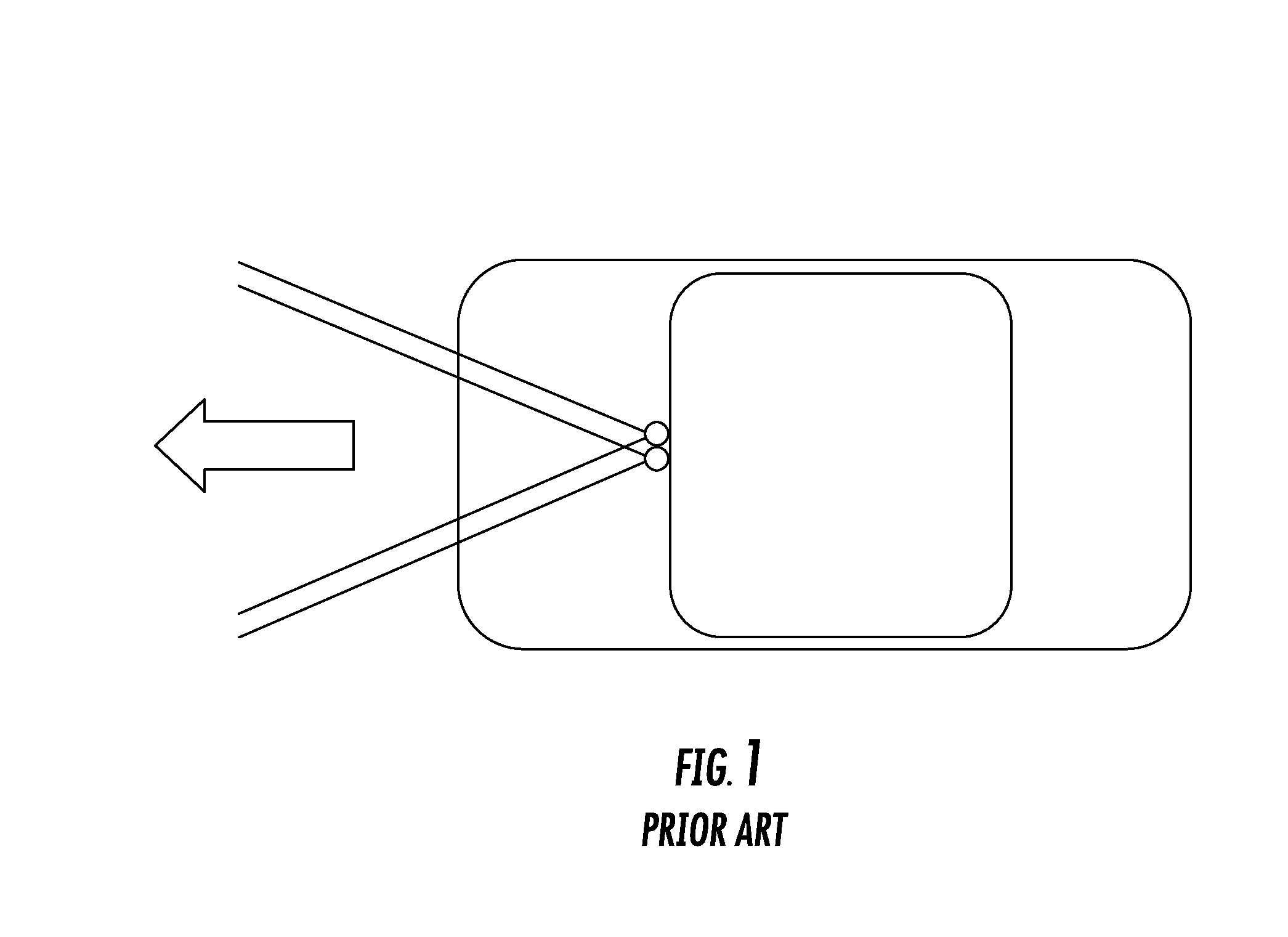
a technology for imaging systems and vehicles, applied in the field of automotive camera systems, can solve the problems of affecting the reliability the combined field of view of cameras may not be wide enough to reliably capture, and the failure of safety and advanced driver assistance systems, so as to improve the ability of safety and quality. the effect of quality

Inactive Publication Date: 2016-06-09
UNIVERSITY OF ALABAMA
View PDF4 Cites 11 Cited by
  • Summary
  • Abstract
  • Description
  • Claims
  • Application Information

AI Technical Summary

Benefits of technology

[0005]Various implementations include an automotive imaging system that includes at least three cameras disposed on a vehicle and an electronic control unit (ECU) in electronic communication with the cameras. The three cameras have overlapping fields of view, and a processor of the ECU may be configured for: (1) blending the images captured from the fields of view of the cameras to produce a single panoramic image, (2) generating and blending together at least three stereoscopic images from images captured by each pair of cameras, and (3) identifying at least one optimal camera setting for each of one or more cameras based on a plurality of images sequentially taken by the camera at different camera settings. Generating and blending stereoscopic images from images captured by each pair of cameras provides a high quality (or resolution) stereoscopic panoramic image. These images provide a wider field of coverage and improved images, which improves the ability of the safety and advanced driver assistance systems of the vehicle to detect and identify potential collision hazards and conduct situational analyses of the vehicle according to certain implementations.

Problems solved by technology

However, this stereo camera system has some drawbacks that may affect the reliability of the safety and advanced driver assistance systems.
In particular, the combined field of view of the cameras may not wide enough to reliably capture all images that may be in front of the vehicle without giving up resolution or capturing distorted images.
In addition, if one of the two cameras malfunctions during a critical maneuver, or driving event, the camera system would lose its ability to generate a stereoscopic image, which could cause the safety and advanced driver assistance systems to fail.
Furthermore, images captured by cameras that have low resolution decrease the ability of the safety and advanced driver assistance systems to detect and recognize objects that may pose collision or safety risks for the vehicle.

Method used


Image

  • Automotive imaging system
  • Automotive imaging system
  • Automotive imaging system

Examples


Embodiment Construction

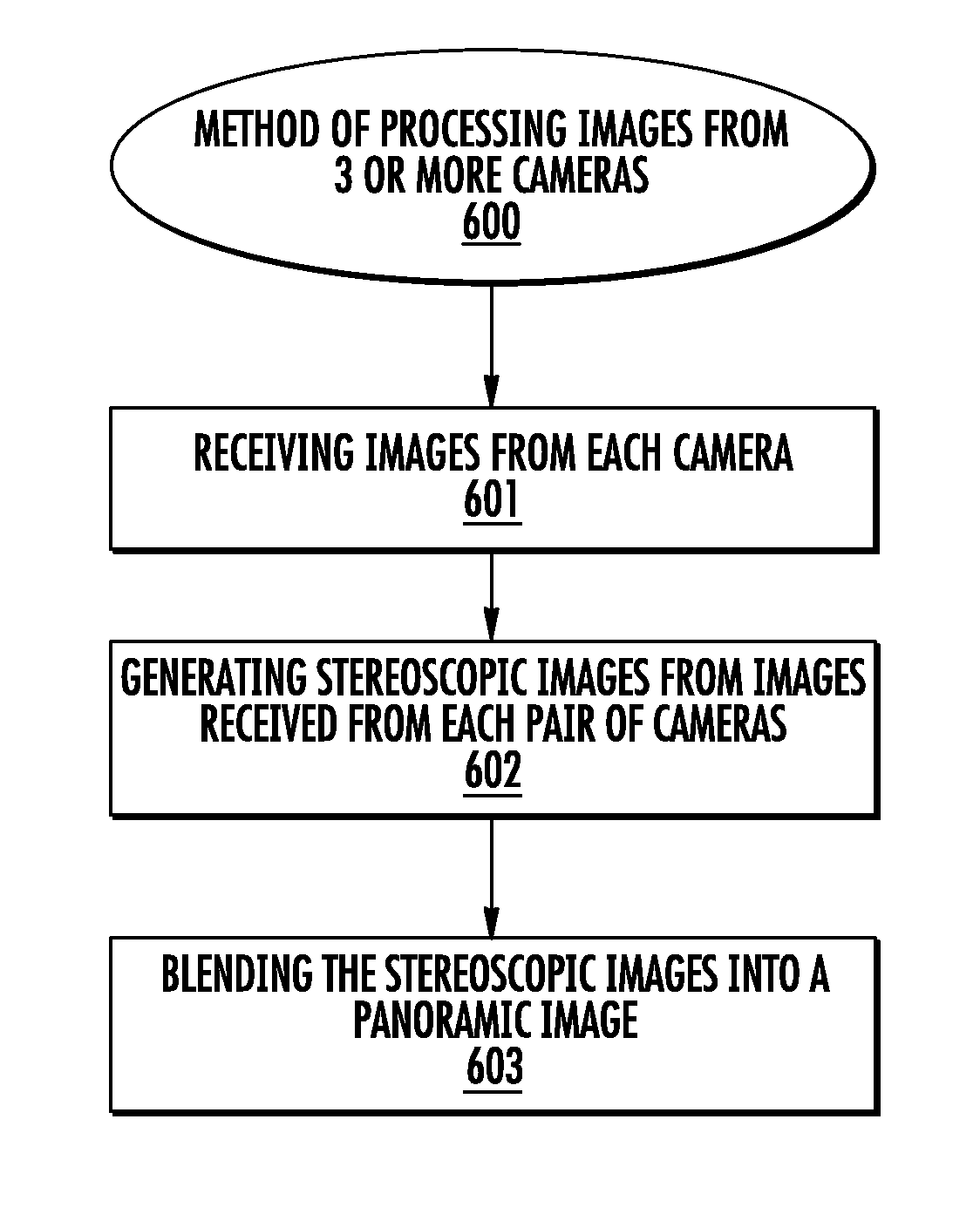
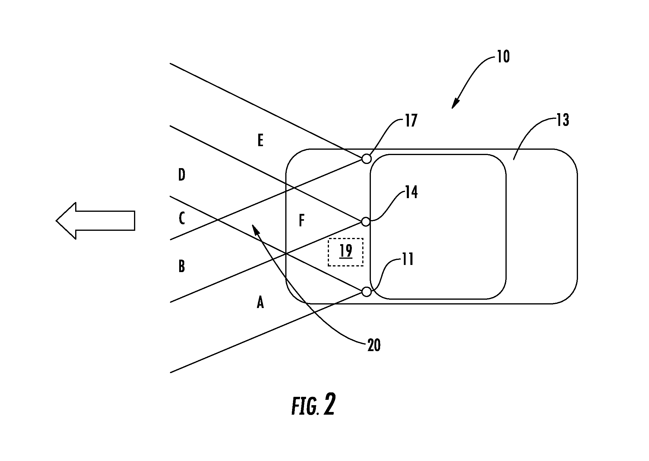
[0017]Various implementations include an automotive imaging system that includes at least three cameras disposed on a vehicle and an electronic control unit (ECU) in electronic communication with the cameras. The three cameras have overlapping fields of view, and a processor of the ECU may be configured for: (1) blending the images captured from the fields of view of the cameras to produce a single panoramic image, (2) generating and blending together at least three stereoscopic images from images captured by each pair of cameras, and (3) identifying at least one optimal camera setting for each of one or more cameras based on a plurality of images sequentially taken by the camera at different camera settings. Generating and blending stereoscopic images from images captured by each pair of cameras provides a high quality (or resolution) stereoscopic panoramic image. These images provide a wider field of coverage and improved images, which improves the ability of the safety and advanc...


PUM


Abstract

Various implementations include an automotive imaging system that includes at least three cameras disposed on a vehicle and an electronic control unit (ECU) in electronic communication with the cameras. The three cameras have overlapping fields of view, and a processor of the ECU may be configured for generating at least three stereoscopic images from images captured by each pair of cameras and blending these stereoscopic images into one high quality panoramic image. These images provide a wider field of coverage and improved images, which improves the ability of the safety and advanced driver assistance systems of the vehicle to detect and identify potential collision hazards and conduct situational analyses of the vehicle according to certain implementations.

Description

CROSS-REFERENCE TO RELATED APPLICATIONS[0001]This application claims priority to U.S. Provisional Patent Application No. 62 / 088,933, filed Dec. 8, 2014, and entitled “AUTOMOTIVE IMAGING SYSTEM,” the entire disclosure of which is incorporated herein by reference.BACKGROUND[0002]Known automotive camera systems may include a pair of fixed cameras (e.g., stereovision cameras) disposed adjacent the rear view mirror on the front windshield that has a combined field of view extending in front of the vehicle of about 40° to about 60°. An exemplary set up is shown in FIG. 1. The images from this camera pair may be used to generate three-dimensional, or stereoscopic, images of objects within the field of views of the cameras. These stereoscopic images are used for object detection and collision avoidance by safety and advanced driver assistance systems of the vehicle. For example, the vehicle may use the images for detecting objects that are in the path of the vehicle and identifying the obje...

Claims


Application Information

Patent Timeline
Patent Type & Authority Applications(United States)
IPC IPC(8): H04N13/02B60R11/04B60R1/00H04N5/232
CPCH04N13/0242H04N5/23238H04N2013/0088B60R1/00B60R11/04B60R2300/105B60R2300/107B60R2300/303B60R2300/406H04N13/296H04N13/243H04N23/698
Inventor BALASUBRAMANIAN, BHARAT
Owner UNIVERSITY OF ALABAMA
Why Eureka
Try Eureka