Luggage case structure

Inactive Publication Date: 2016-06-16
LAI WEI HUNG
View PDF4 Cites 32 Cited by
  • Summary
  • Abstract
  • Description
  • Claims
  • Application Information

AI Technical Summary

Benefits of technology

[0008]The primary objective of the present invention is to provide a luggage case structure, wherein the aluminum alloy frames extends in depth to the bottom of the two shells to form the four lateral surfaces of the two shells, which solves the problem of structure strength difference between t

Problems solved by technology

Therefore, carbon product has relatively high tensile strength but is susceptible to crack, and the carbon fiber product is particularly weak at the folding portion.
Once

Method used


Image

  • Luggage case structure
  • Luggage case structure
  • Luggage case structure

Examples


Example

[0021]The present invention will be clearer from the following description when viewed together with the accompanying drawings, which show, for purpose of illustrations only, the preferred embodiment in accordance with the present invention.

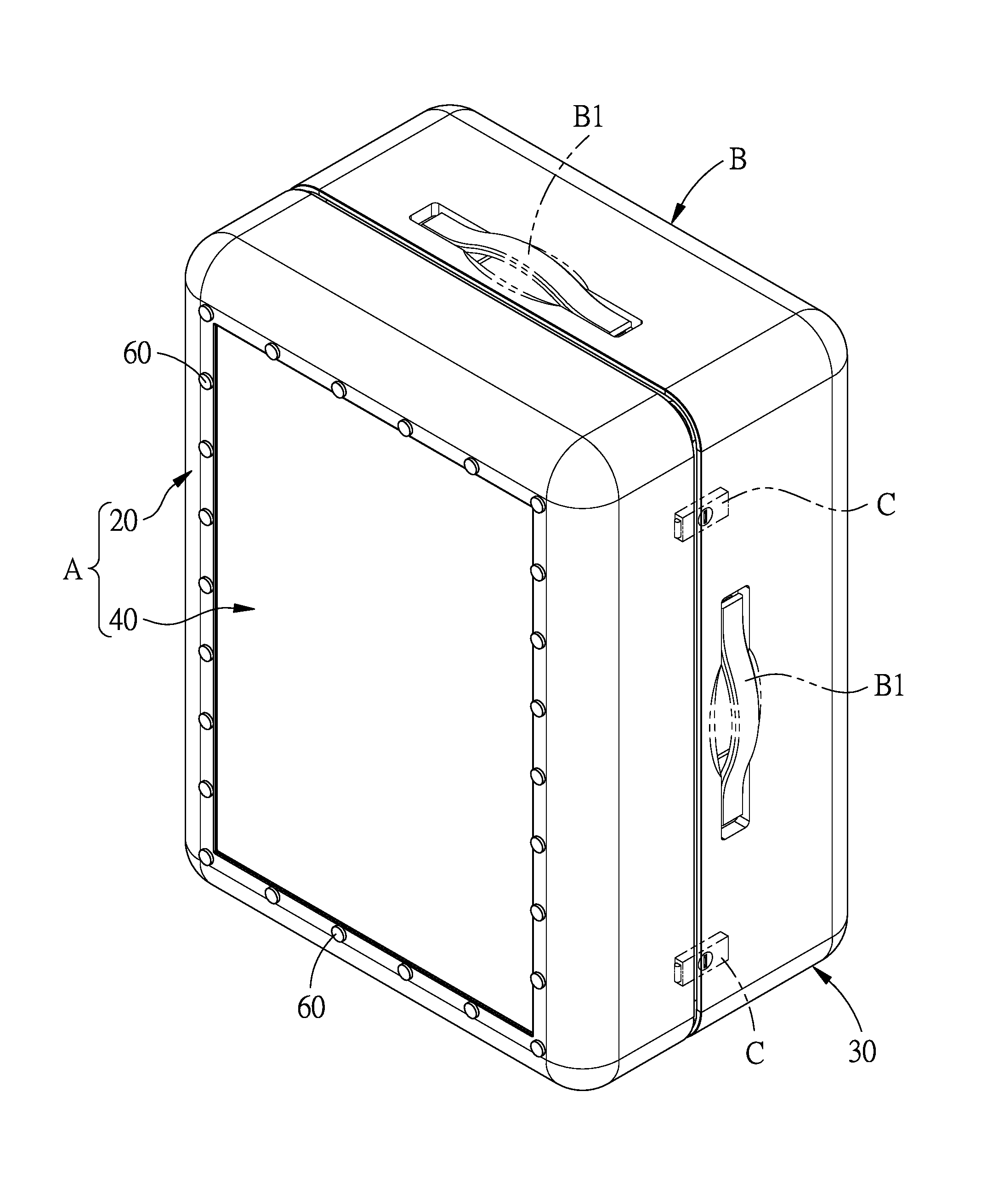
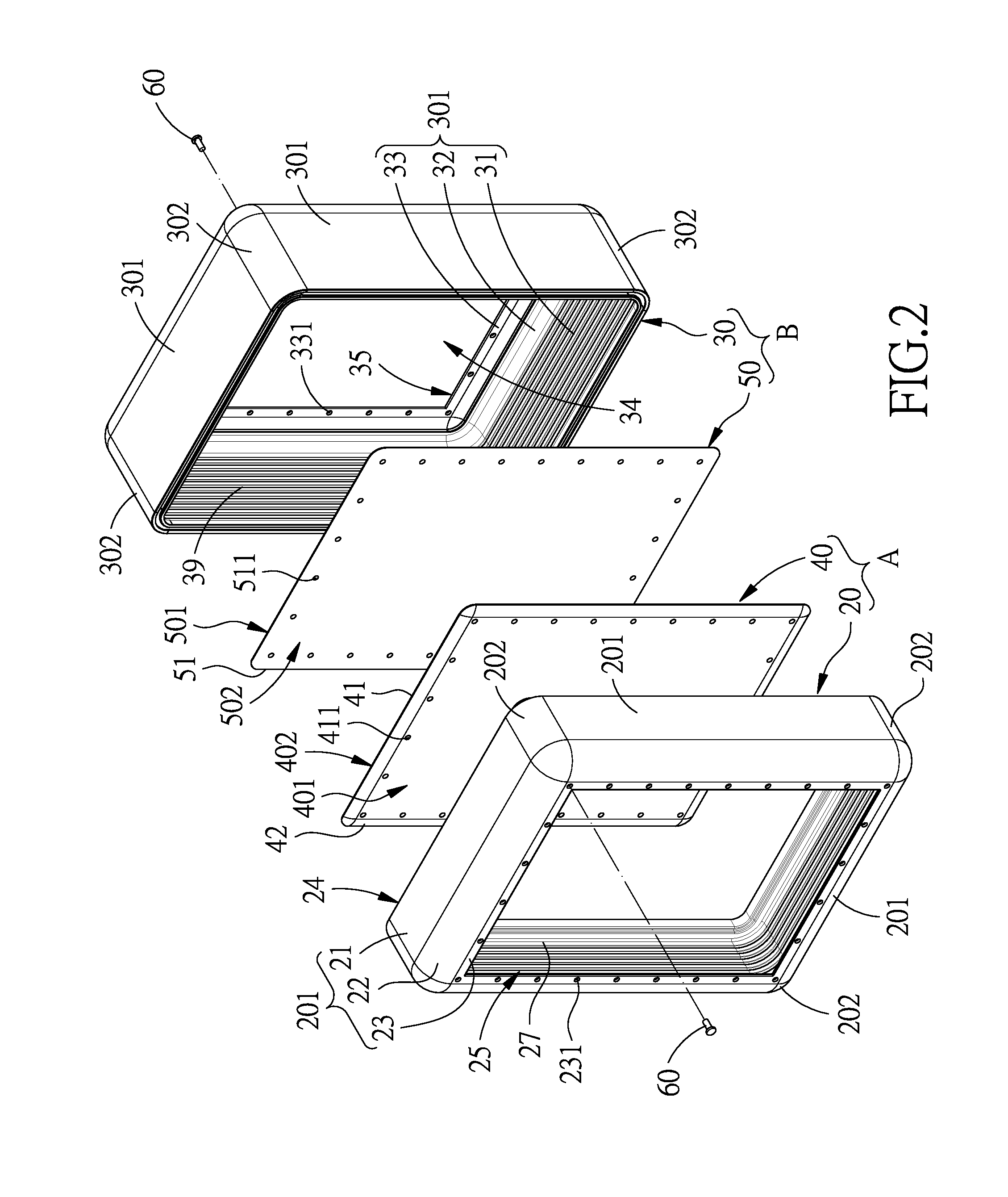
[0022]Referring to FIGS. 2-6, a luggage case structure in accordance with a preferred embodiment of the present invention comprises two shells, namely, a first shell A and a second shell B. The first shell A includes a first frame 20 and a first board 40 which are connected to each other by a plurality of fasteners 60. The second shell B includes a second frame 30 and a second board 50 which are connected to each other by a plurality of fasteners 60. The means for connecting the first frame 20 and the first board 40 or the second frame 30 and the second board 50 is not limited to the fasteners 60, and can also be gluing, or the combination of the two, in order to improve the connection strength between the frame and the board. Or, the connecting ...


PUM


Abstract

A luggage case structure is provided with two aluminum alloy frames which extend in depth to the bottom of the two shells to form the four lateral surfaces of the two shells, which solves the problem of structure strength difference between the bottom of the shells of the convention luggage case and the lateral boards. Besides, the carbon fiber is formed into two-dimensional flat boards instead of a three-dimensional structure, which not only makes manufacturing easier, but also enhances the structural strength while reducing weight.

Description

BACKGROUND OF THE INVENTION[0001]1. Field of the Invention[0002]The present invention relates to a case, and more particularly to a luggage case structure.[0003]2. Description of the Prior Art[0004]The existing luggage cases are generally divided into soft cases and hard cases. Hard cases have better ability to resist deformation and therefore win more market share. In order to reduce the weight of the hard case, as shown in FIG. 1, a carbon fiber luggage case 10 was developed and comprises two opposite hard shells 11 which are formed by hot vacuum molding of carbon fibers. Each of the shells 11 includes a bottom 111 and four lateral boards 112, 113, 114, 115 which are integrally formed around the bottom 111 to define a chamber 116. The two shells 11 are connected to each other by a first frame 12, a second frame 13 and hinges 14 to form the luggage case 10.[0005]The first frame 12 is relatively narrow and disposed around the periphery of the chamber 116 of the front shell 11 of the...

Claims


Application Information

Patent Timeline
IPC IPC(8): A45C5/03A45C13/00A45C13/04A45C5/02
CPCA45C5/03A45C5/02A45C2005/037A45C13/005A45C13/04A45C13/002
Inventor LAI, WEI-HUNG
Owner LAI WEI HUNG
Why Eureka
Try Eureka