Cover material fastening clip

a technology of fastening clip and cover material, which is applied in the direction of vehicle components, chairs, vehicle arrangements, etc., can solve the problems of troublesome operation of locking the hook piece, poor workability, and difficult operation, and achieves convenient and satisfactorily hooked, easy to lock the hook portion, and simple operation

Active Publication Date: 2016-06-16
YKK CORP
View PDF14 Cites 13 Cited by
  • Summary
  • Abstract
  • Description
  • Claims
  • Application Information

AI Technical Summary

Benefits of technology

[0019]In the cover material fastening clip according to the aspect of the embodiments of the present invention, it is possible to easily lock the hook portion to the wire in a cushion material or the like with a simple operation and thus to surely install the cover material in the cushion material. Even when the cover material fastening clip is inclined by pressing the cover material fastening clip from the upper side with a finger in a locking operation, the wire can be easily and satisfactorily hooked to the hook portion in the inclined state and thus working efficiency is good. Since the leading passage is formed toward the insertion opening of the hook portion into which the wire is inserted such that the extensions of a pair of guide surfaces intersect each other, it is not necessary to accurately position the wire and it is possible to guide the wire in a wide range. Accordingly, it is possible to satisfactorily guide and hook the wire to the insertion opening.
[0020]Since the leading end portions of the first upper guide surface and the second upper guide surface extend laterally from the leading end portion of the first hook piece or the second hook piece, it is possible to easily and satisfactorily guide the wire to the locking position in the holding space and to decrease a movable range of the wire in the locked state to easily maintain the locked state.

Problems solved by technology

In this case, the posture of the hook piece needs to be changed and the hook piece needs to be inserted again, thereby making an operation of locking the hook piece troublesome.
Accordingly, workability was poor and the operation was not easy.
Accordingly, it is difficult to engage the wire with the hook piece.
Accordingly, a large force is required and it is difficult to use the hook member.
Accordingly, when the hook member is removed from the wire, the operation has to be carried out while holding the closing piece in an opened state and thus it is difficult to carry out the operation.
However, since it is difficult to see the position of the wire, it is difficult to engage the wire with the hook.

Method used


Image

  • Cover material fastening clip
  • Cover material fastening clip
  • Cover material fastening clip

Examples


first embodiment

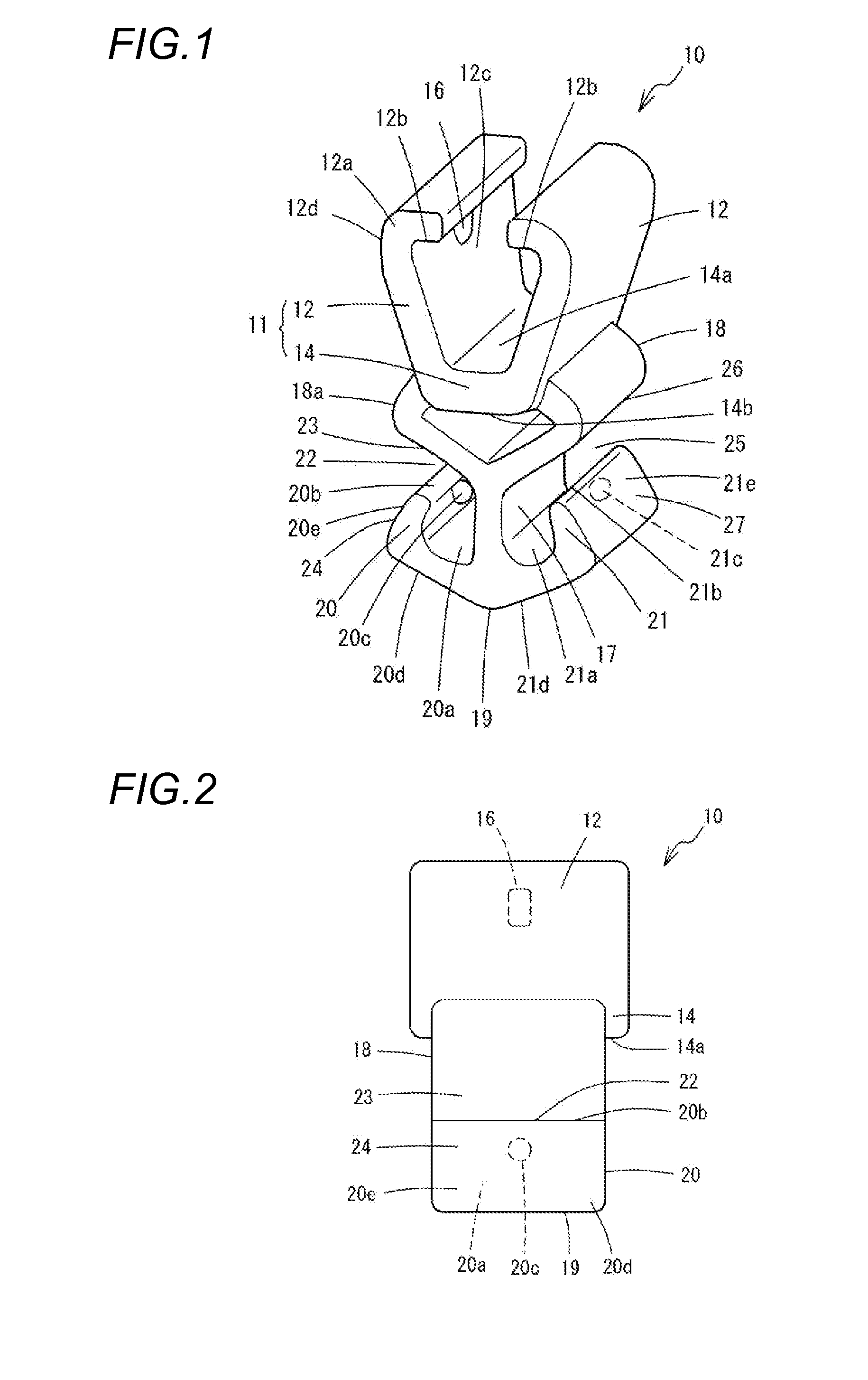
[0040]FIGS. 1 and 2 illustrate the present invention, the cover material fastening clip 10 according to this embodiment is formed as a unified body out of a synthetic resin and includes a pair of locking claws 12. The locking claws 12 include arms 12d which are formed to face each other. Base end portions of the arms 12d (base end portions of the locking claws 12) are formed as a unified body on both sides of a top surface 14a of a locking claw base portion 14 (also referred to as one surface of the locking claw base portion 14). The locking claws 12 protrude from the top surface 14a upward in FIG. 1 and are formed such that a gap in the horizontal direction therebetween increases upward. A locking portion 11 is constituted by the locking claws 12 and the locking claw base portion 14. Leading end portions 12a of the locking claws 12 are bent inward, that is, in a direction in which both approach each other. Each leading end portion 12a includes a locking surface 12b which is located...

second embodiment

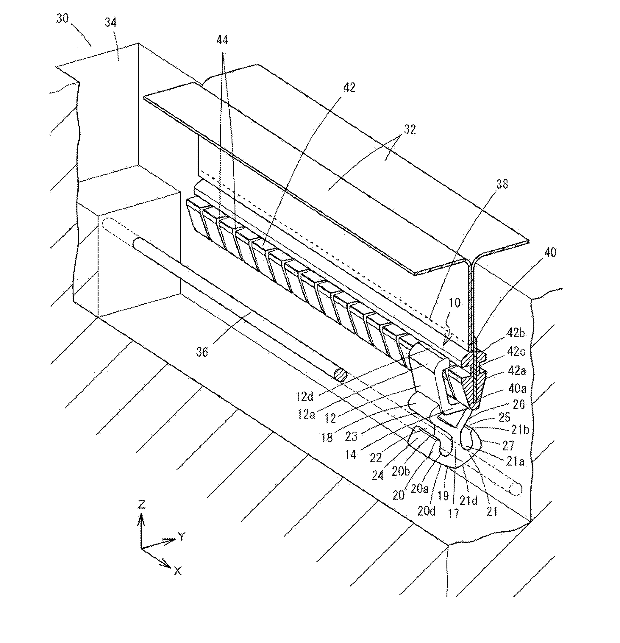
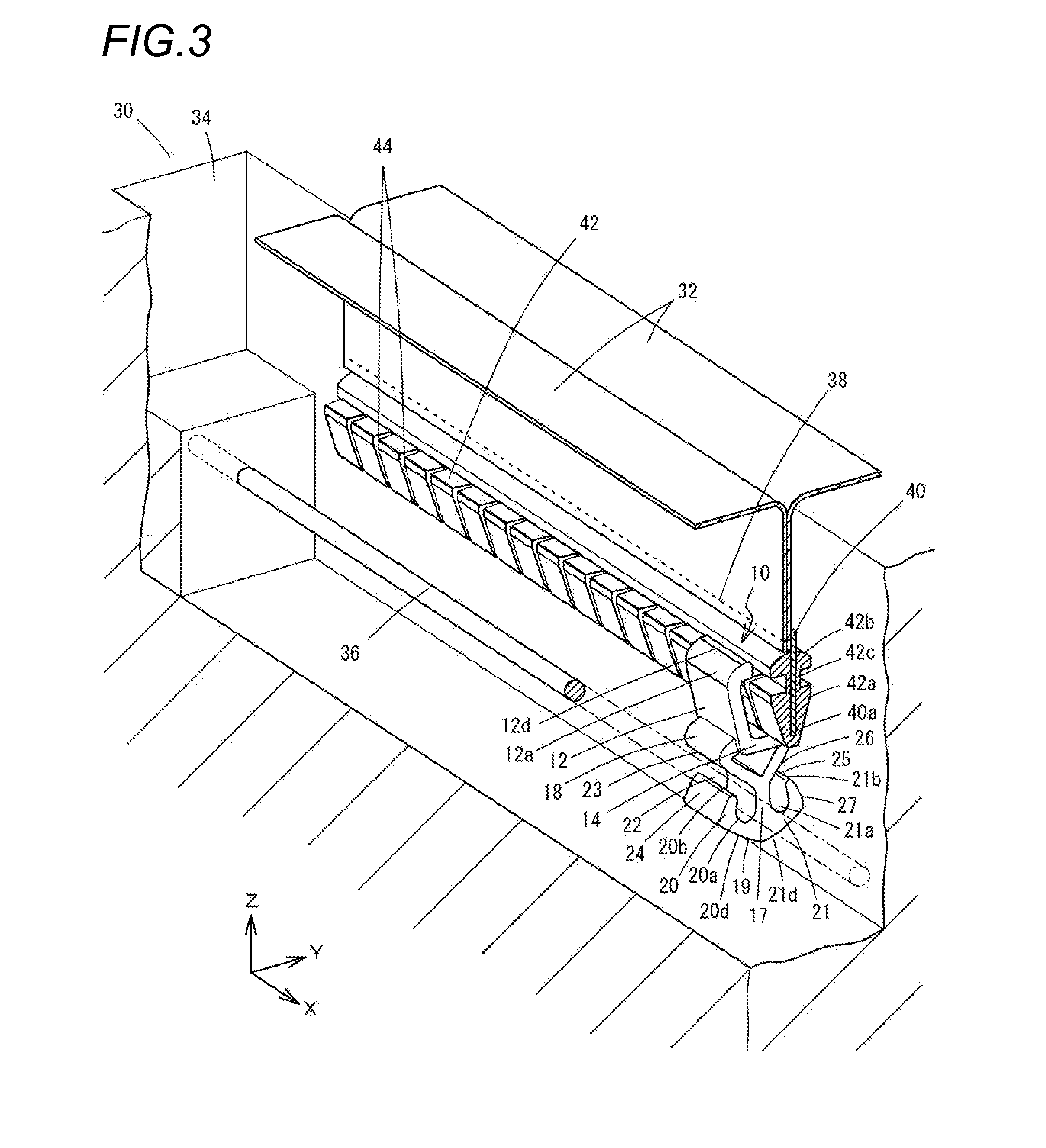
[0064]the present invention will be described below with reference to FIG. 12. Here, the same members as in the above-mentioned embodiment will be referenced by the same reference numerals and description thereof will not be repeated. In a cover material fastening clip 54 according to this embodiment, a guide portion 56 is formed in a block shape as a unified body along with the locking claw base portion 14. The guide portion 56 is connected to the opposite surface of the top surface 14a of the locking claw base portion 14 and the extending portion 17 and is formed in a triangular shape in which the portion connected to the extending portion 17 is separated away from the top surface 14a. An oblique side of the guide portion 56 on the first hook piece 20 side serves as a first upper guide surface 58 which is inclined toward the bottom portion of the holding space 20a. Similarly to the above-mentioned embodiment, the contact surface 20e of the first hook piece 20 serves as the first l...

third embodiment

[0067]the present invention will be described below with reference to FIGS. 13 and 14. Here, the same members as in the above-mentioned embodiment will be referenced by the same reference numerals and description thereof will not be repeated. In a cover material fastening clip 62 according to this embodiment, a jig groove 64 to which the locking portion 52b of the jig 46 is fitted is formed along the X axis direction on the bottom portion of the holding space 20a of the first hook piece 20. A part of a cylinder of the jig groove 64 communicates with the inner circumferential surface of the holding space 20a, and the opening 64a communicating with the holding space 20a is set to have a width smaller than the diameter of the jig groove 64. A jig groove 66 having the same shape as the jig groove 64 is formed to be connected via the opening 66a in the second hook piece 21.

[0068]In this embodiment, the diameter of the locking portion 52b of the jig 46 which is used to remove the cover ma...


PUM


Abstract

There is provided a cover material fastening clip for attaching a cover material to a cushion material. The clip is provided with a locking portion, a hook portion and a guide portion. The hook portion is provided with an extending portion that extends downward from the locking portion, a first hook piece a second hook portion. The guide portion is formed in the locking portion or the extending portion and is located above the first and second hook pieces. A space between a leading end portion of the first hook piece and the guide portion serves as a first insertion opening with a predetermined gap into which the wire is inserted. A space between a leading end portion of the second hook piece and the guide portion serves as a second insertion opening with a predetermined gap into which the wire is inserted.

Description

CROSS-REFERENCE TO RELATED APPLICATION[0001]The present application claims priority of Japanese Patent Application No. 2014-249726, filed on Dec. 10, 2014 and entitled “Cover Material Fastening Clip”, the entire contents of which are hereby incorporated by reference.TECHNICAL FIELD[0002]The present invention relates to a cover material fastening clip which is used to fasten a cover material covering the surface of a chair, a seat, or the like.BACKGROUND[0003]In the related art, in a chair used in a room, a seat in a vehicle, or the like, a cushion material or a soft pad is frequently used in a portion to be touched by a human body, such as a seat surface or a back rest, and the surface thereof is covered with a cover material. Various structures are employed for fastening such a cover material. As a structure capable of fastening the cover material and visually being concealed, there has been known a structure in which a wire is disposed in a groove of the cushion material, clips ar...

Claims


Application Information

Patent Timeline
Patent Type & Authority Applications(United States)
IPC IPC(8): B60N2/58B60N2/70A47C7/24
CPCB60N2/5825B60N2/70A47C7/24A47C31/023
Inventor MURASAKI, RYUICHIMATSUMURA, GENTAYOSHIDA, TOMONARIIYODA, YOSHITOMOSAIGA, SHINSUKE
Owner YKK CORP
Why Eureka
Try Eureka