
Mechanoluminescent display device

a technology of mechanoluminescent display and display device, which is applied in the direction of light sources, lighting and heating apparatus, and mechanoluminescent applications, etc., can solve the problems of limited studies related to mechanoluminescence, low industrial applicability, and limited lifetim

Active Publication Date: 2016-06-16
DAEGU GYEONGBUK INST OF SCI & TECH
View PDF4 Cites 4 Cited by
  • Summary
  • Abstract
  • Description
  • Claims
  • Application Information

AI Technical Summary

Benefits of technology

The present invention spreads the use of a mechanoluminescent phenomenon from a conventional academic study to various industries such as lighting, display, biology (e.g. artificial skin), and imaging. This technology converts mechanical energy into light energy without needing external power, which is environmentally friendly and can be used as a solution to resource and oil price crises.

Problems solved by technology

Nature 2006), etc. caused a great response academically, but industrial applicability is very low due to a fundamental problem that the light is generated by friction or destruction.
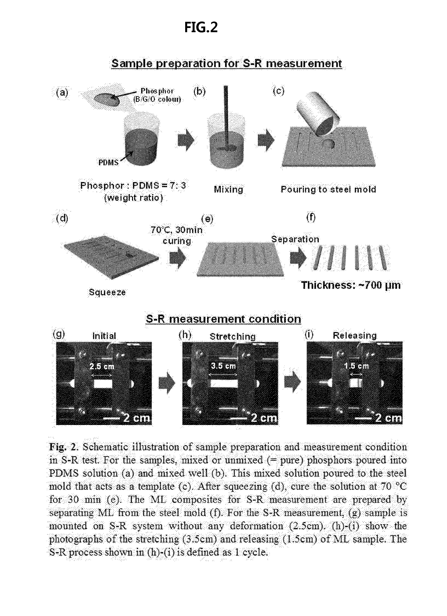
However, a UV cured polymer is used as a stress transmission material transmitting a mechanical strength to a luminescent material, which is a parent material of emitting light, and thus a lifetime is extremely limited since it is difficult to apply repeated stresses.
Further, studies related to the mechanoluminescence are limited to the luminescent material itself until now, and there are no studies related to the stress transmission material transmitting the stress.
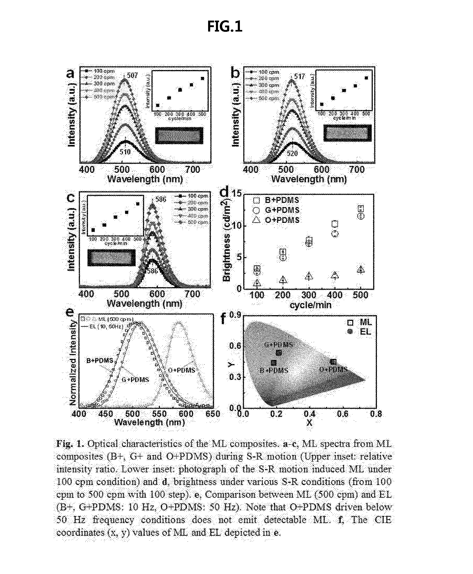
Further, in order to apply the mechanoluminescent phenomenon to various industries, brightness, a lifetime, and a color control are very important factors, but many studies have not been performed due to a limitation of the material itself until now.
Particularly, technological developments related to the color control do not exist due to the brightness of the light emitted from the material and the limitation of the lifetime (or reproducibility).

Method used


Image

  • Mechanoluminescent display device
  • Mechanoluminescent display device
  • Mechanoluminescent display device

Examples


Embodiment Construction

[0024]The above and other objects, features and advantages of the present invention will become more apparent with reference to exemplary embodiments which will be described hereinafter with reference to the accompanying drawings. However, the present invention is not limited to exemplary embodiments which will be described hereinafter, and can be implemented by various different types. Exemplary embodiments of the present invention are described below in sufficient detail to enable those of ordinary skill in the art to embody and practice the present invention. The present invention is defined by claims. Meanwhile, the terminology used herein to describe exemplary embodiments of the invention is not intended to limit the scope of the invention. The articles “a,”“an,” and “the” are singular in that they have a single referent, but the use of the singular form in the present document should not preclude the presence of more than one referent.

[0025]Hereinafter, exemplary embodiments o...


PUM


Abstract

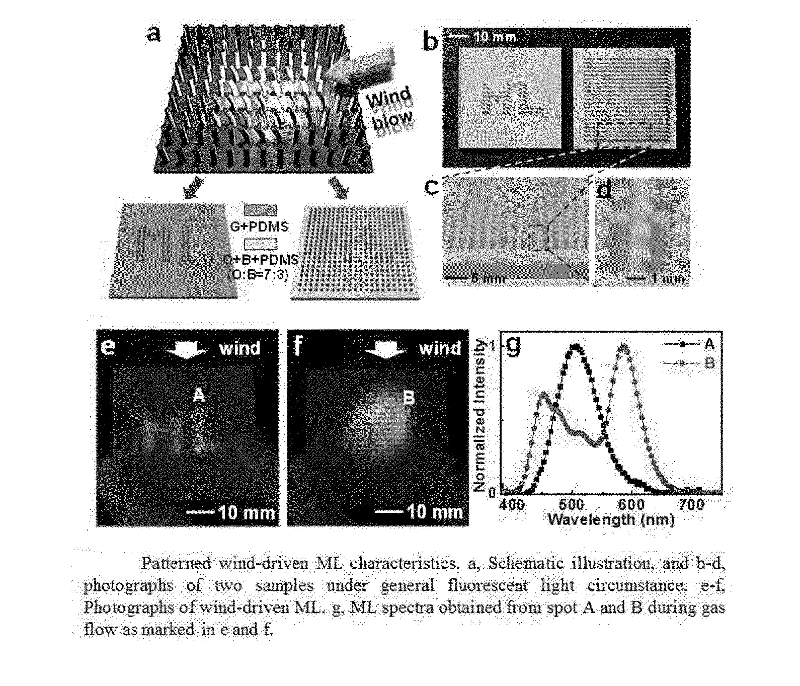
Provided is a display device in a mechanical method using wind, vibration. The mechanoluminescent display device includes a substrate having a predetermined shape, and projections formed with a predetermined pattern on the substrate. The projections are formed of a mixture of a stress luminescent material emitting light by mechanical energy which is applied and a stress transmission material transmitting the mechanical energy applied from the outside to the stress luminescent material.

Description

TECHNICAL FIELD[0001]The following description relates to a display device, and more particularly, to a display device emitting light in a mechanical method using wind and vibration.BACKGROUND ART[0002]A phenomenon of emitting light in a mechanical method, that is, light generated by applying a strength to a material has been known as mechanoluminescence (a superordinate concept including triboluminescence, fractoluminescence, deformation-luminescence, etc.) for a long time, but a principle of emitting the light is uncertain even until now and also has been treated as only an academic interest.[0003]For example, X-ray emission due to a separation phenomenon of scotch tape in a vacuum (Camara et al. Nature 2008) and ultraviolet (UV) ray emission due to an ultrasonic wave (Eddingsaas et al. Nature 2006), etc. caused a great response academically, but industrial applicability is very low due to a fundamental problem that the light is generated by friction or destruction.[0004]In order ...

Claims


Application Information

Patent Timeline
IPC IPC(8): F21K2/04
CPCF21K2/04G09F9/37G09F19/12C09K11/08
Inventor JEONG, SOON MOONSONG, SEONG KYU
Owner DAEGU GYEONGBUK INST OF SCI & TECH
Learn More