Cell suction system, and method for performing suction work of intracellular substance using the same

a cell suction system and intracellular substance technology, applied in the field of cell suction system and method for performing suction work of intracellular substance using the same, can solve the problems of unsuitable method for processing a lot of cells, difficult to precisely pick up a substance in a desired cell with such positional precision, etc., and achieve the effect of high flexibility

Active Publication Date: 2016-06-16
YOKOGAWA ELECTRIC CORP
View PDF3 Cites 7 Cited by
  • Summary
  • Abstract
  • Description
  • Claims
  • Application Information

AI Technical Summary

Benefits of technology

This patent describes a new device called a cell suction system which has several key features: It uses a special tool (called a suction section) to remove material from cells within a container, it also has a sensor at its front edge to help find the correct cell to extract the material from, and there is a mechanism that lets us move the suction section around in 3D space to make sure we are always aligned correctly with the right cell. With this technology, researchers will no longer have to rely solely upon their own visual sight when trying to locate a particular cell or area of interest. Instead, they will know with certainty where the front edge of the suction tool is located, allowing them to construct highly flexible systems designed specifically for each individual cell being studied.

Problems solved by technology

The technical problem addressed in this patent text relates to improving the accuracy and efficiency of identifying and analyzing intracellular substances for drug discovery purposes. Existing methods require significant amounts of time and effort to determine which cells should be analyzed and can result in poor sensitivity due to imprecise placement of the analyzer's tip. There is thus a need for more efficient and precise techniques for detecting and characterizing these important targets.

Method used


Image

  • Cell suction system, and method for performing suction work of intracellular substance using the same
  • Cell suction system, and method for performing suction work of intracellular substance using the same
  • Cell suction system, and method for performing suction work of intracellular substance using the same

Examples


first preferred embodiment

Light-Receiving Part that Constitutes Signal-Processing Unit is “Confocal Point Optical Type”

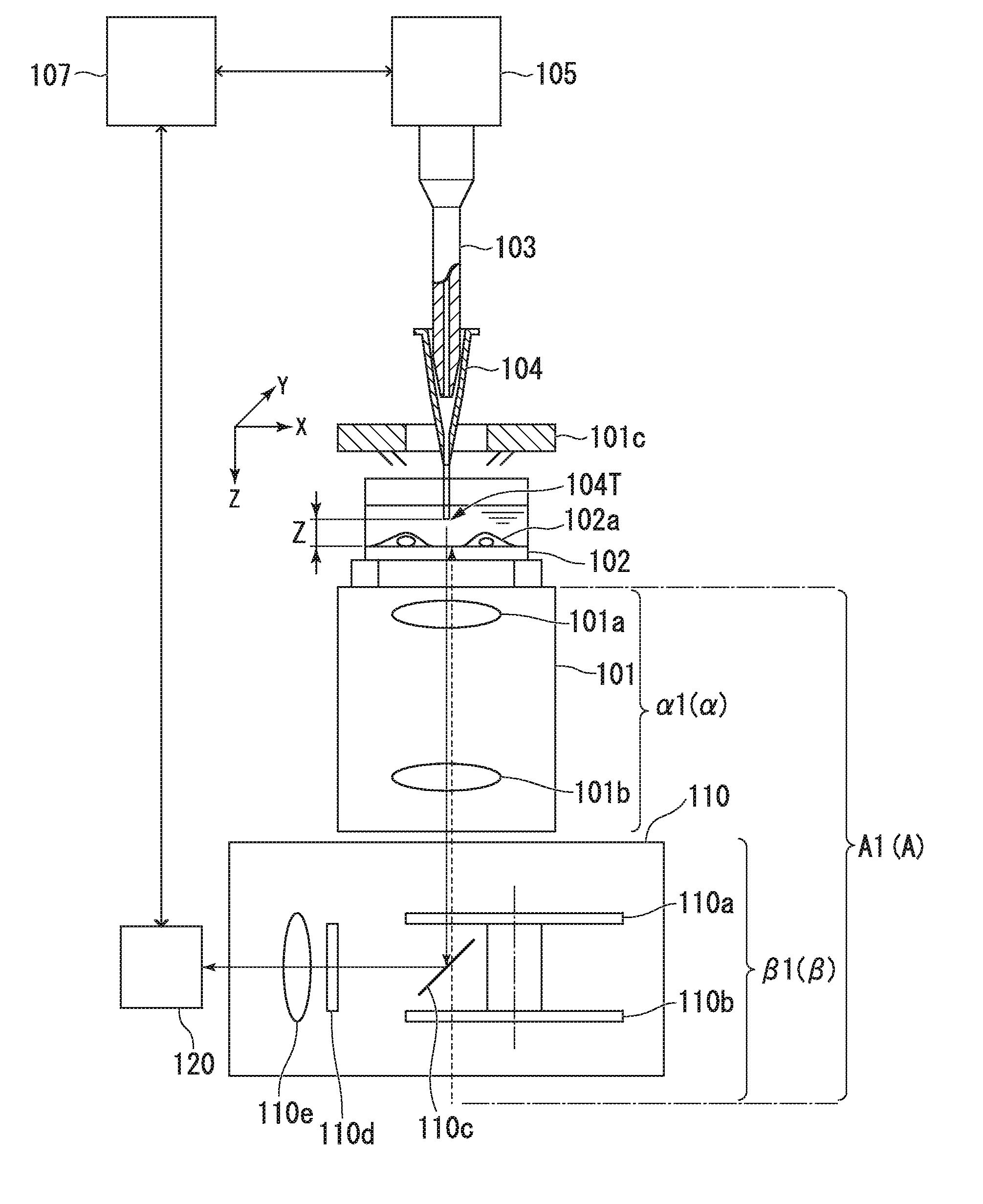
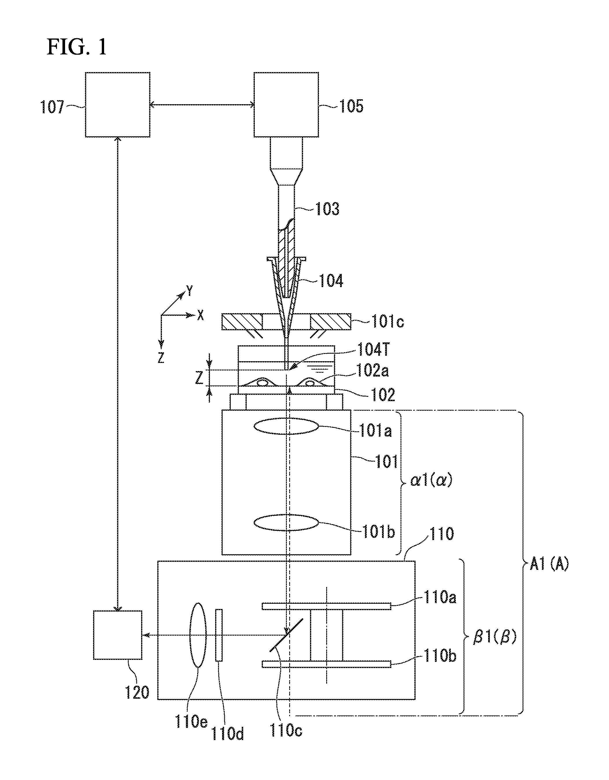
[0033]FIG. 1 is a view illustrating a configuration example of a cell suction system related to a first preferred embodiment of the invention. The cell suction system illustrated in FIG. 1 supports suction work of an intracellular substance. However, the invention may be applied to a cell suction system that suctions one cell or a number of cells if necessary.

[0034]In the cell suction system illustrated in FIG. 1, a cell (sample) 102a and a culture solution are received in a container (sample holder) 102. The cell suction system includes a suction section 103 (dispenser) in which a front end that suctions an intracellular substance (mark O in the drawing) from the inside of the cell (sample) 102a received in the container (sample holder) 102 includes a tubular tip (suction tip) 104, a detection section A1(A) for acquiring information on a front end part 104T of the tip 104, and a conveyance ...

second preferred embodiment

Light-Receiving Part that Constitutes Signal-Processing Unit Ss “Confocal Point Optical Type”

[0044]FIG. 4 is a view illustrating a configuration example of a cell suction system related to a second preferred embodiment of the invention. The cell suction system illustrated in FIG. 4 supports suction work of an intracellular substance. However, the invention may be applied to a cell suction system that suctions one cell or a number of cells if necessary.

[0045]In the cell suction system illustrated in FIG. 4, a cell (sample) 402a and a culture solution are received in a container (sample holder) 402. The cell suction system includes a suction section 403 (dispenser) in which a front end that suctions an intracellular substance (mark O in the drawing) from the inside of the cell (sample) 402a received in the container (sample holder) 402 includes a tubular tip (suction tip) 404, a detection section A4(A) for acquiring information on a front end part 404T of the tip 404, and a conveyance...

third preferred embodiment

Light-Receiving Part that Constitutes Signal-Processing Unit is “Astigmatic Type”

[0058]FIG. 6 is a view illustrating a configuration example of a cell suction system related to a third preferred embodiment of the invention. The cell suction system illustrated in FIG. 6 supports suction work of an intracellular substance. However, the invention may be applied to a cell suction system that suctions one cell or a number of cells if necessary.

[0059]In the third preferred embodiment (FIG. 6), the light-receiving part is an astigmatic type, and a cylindrical lens 606gA is used instead of the condensing lens in the aforementioned second preferred embodiment (FIG. 4). A pinhole 406h in the second preferred embodiment (FIG. 4) is made unnecessary. A quadripartite PD (photodiode) is used as the light-receiving sensor 606iA. The other components are the same as those of the second preferred embodiment (FIG. 4). However, in order to be distinguished from the second preferred embodiment (FIG. 4)...


PUM


Abstract

Provided is a cell suction system that supports suction work of a substance within a cell. The cell suction system includes: a suction section including a tubular tip configured to suction the substance from the inside of the cell received in a container; a detection section configured to acquire information on a front end part of the tip; and a conveyance section configured to make the suction section three-dimensionally movable, the conveyance section being configured to move the suction section to guide the front end part of the tip attached to the suction section into one specific cell based on the information obtained in the detection section.

Description


Claims


Application Information

Patent Timeline
Owner YOKOGAWA ELECTRIC CORP
Why Eureka
Try Eureka