
Calibration of microscopy systems

a microscopy system and microscopy technology, applied in the field of microscope calibration, can solve the problems of affecting the accuracy the validity of the master microscope becoming vulnerable to changes or failures of the master microscope, and the microscope could suffer a change or degradation in one or more properties

Active Publication Date: 2016-06-16
LEICA MICROSYSTEMS CMS GMBH
View PDF3 Cites 14 Cited by
  • Summary
  • Abstract
  • Description
  • Claims
  • Application Information

AI Technical Summary

Benefits of technology

The patent text describes a method for calibrating different microscopes. A calibration plate is loaded onto the microscope stage and a calibration routine is executed to generate calibration data for the microscope. This calibration data includes information about the microscope's geometry, illumination, and optics. This data is stored on a memory accessible by the microscope. The technical effects of this invention include the ability to easily calibrate different microscopes using one calibration plate, allowing for inter-microscope registry and utilizing the same calibration data for multiple microscopes.

Problems solved by technology

For a given lab with multiple microscopes, one problem arises with regard to load-balancing a fleet of microscopes performing multi-round imaging when, for example, one microscope is down for repair, or, alternatively, is backed up with many tissue samples that are tied to the microscope for the duration of the multi-round imaging process and are waiting for their additional rounds of imaging while other microscopes sit idle.
Among the problems that may exacerbate management of multiple microscopes in such an arrangement is the need to calibrate (e.g., optically, geometrically, illumination, and so forth) all microscopes within a given lab relative to one another so that the layered images that are produced within a given lab are of high quality and are consistent over time, regardless of the microscope employed.
By using a master microscope as the reference, the validity of the calibrations of all microscopes becomes vulnerable to changes or failures of the master microscope.
The problem with this approach is that any microscope could suffer a change or degradation in one or more properties at any time and therefore the validity of the inter-microscope calibrations could always be questioned.

Method used

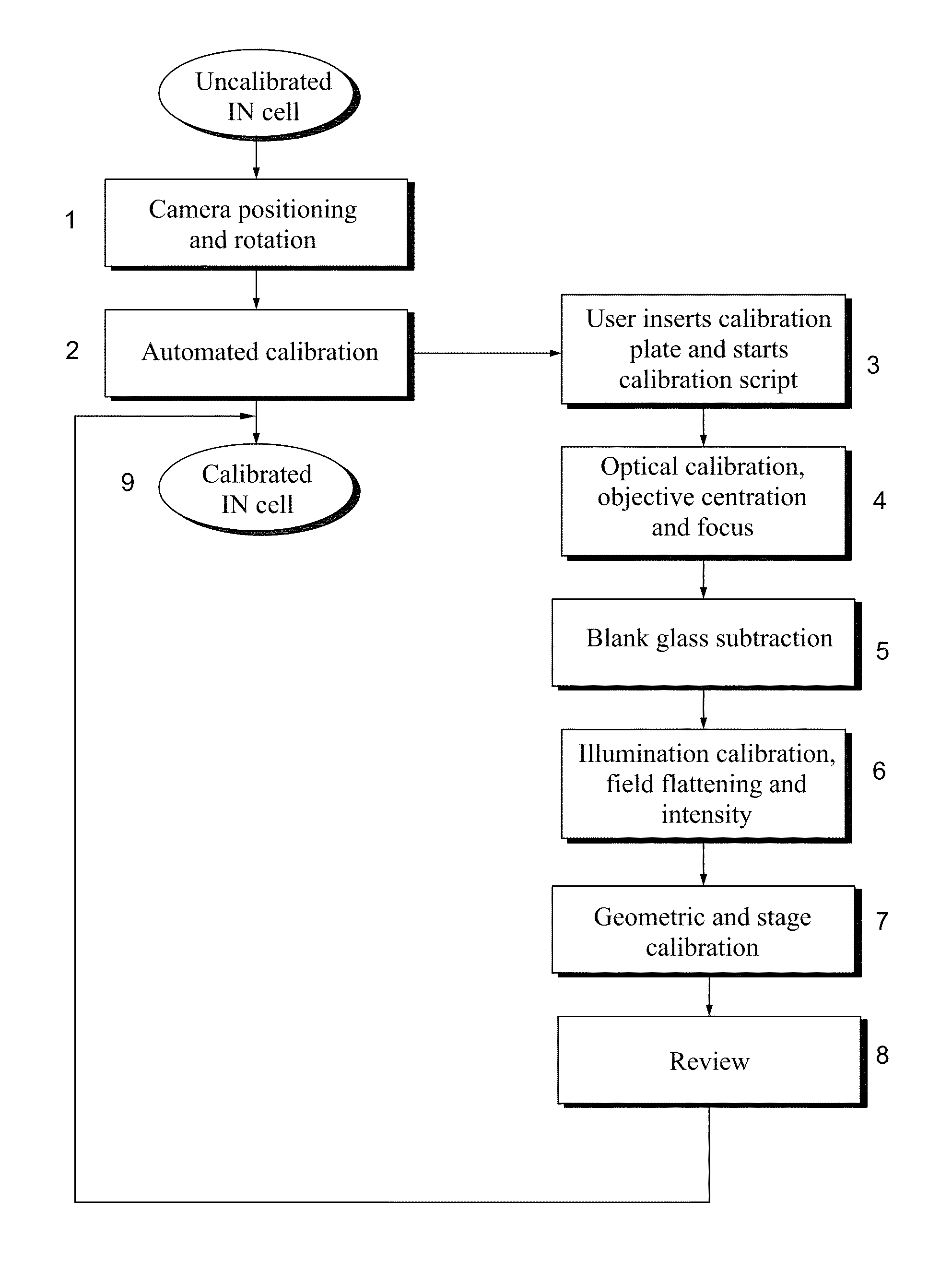
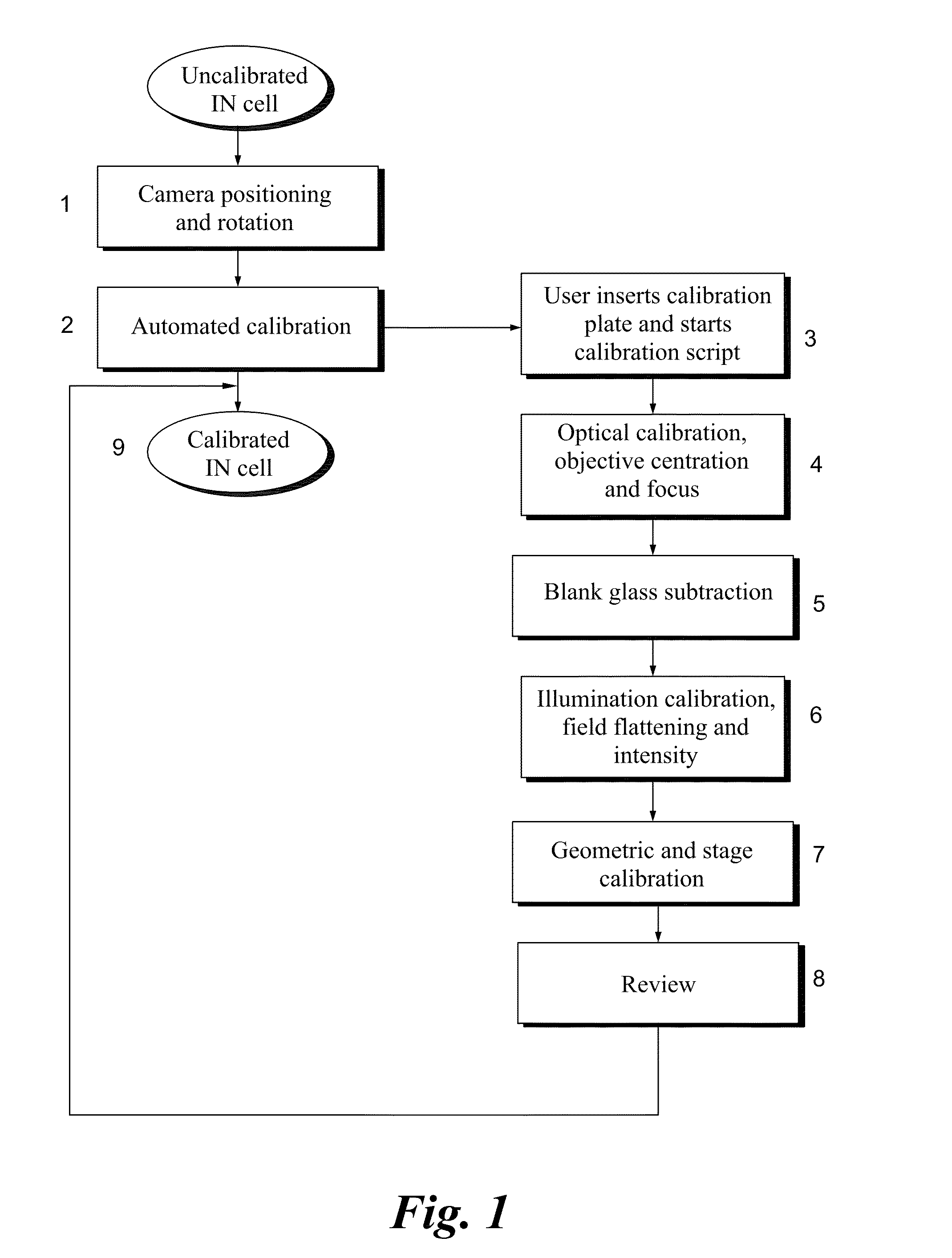
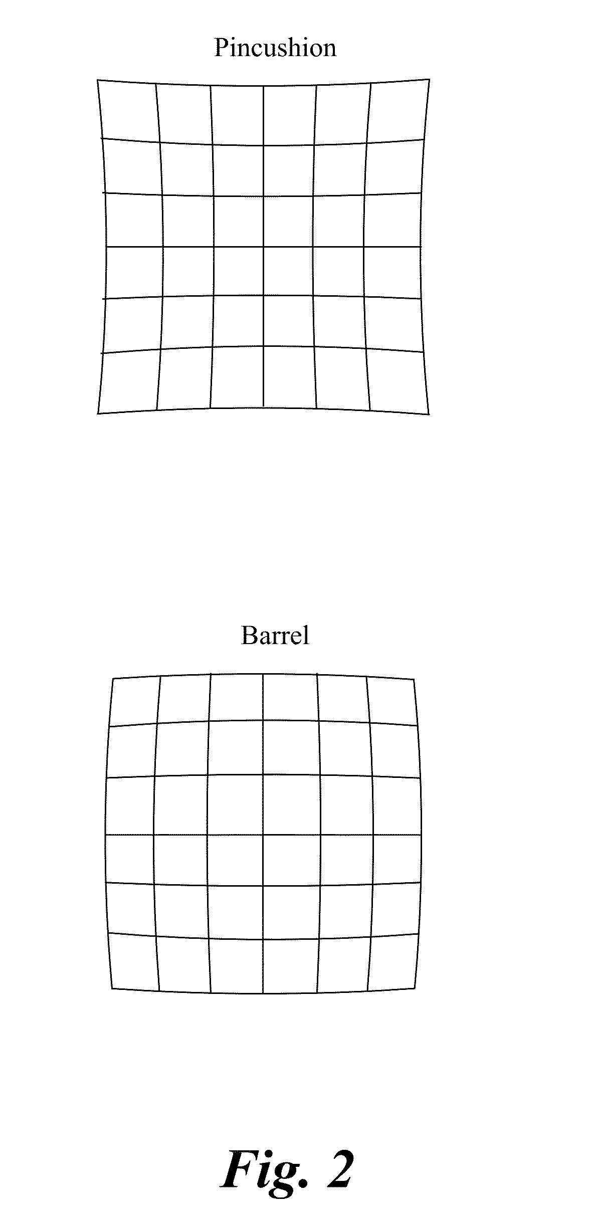

Image

  • Calibration of microscopy systems
  • Calibration of microscopy systems
  • Calibration of microscopy systems

Examples


examples

[0055]As an example, experimental results for a geometric calibration are provided using a single FOV to validate inter-microscope imaging. A single FOV was acquired at the same slide coordinates on multiple microscopes and the positioning of images with and without stage calibration was compared.

[0056]As shown in FIG. 7, a single grid FOV is shown at 10x before and after running inter-microscope stage calibration. The images were obtained on two IN Cell Microscope Analyzer 2200 systems (GE HealthCare Life Sciences, Marlborough, Mass.) and referred to as IN Cell 1 and IN Cell 2 to differentiate the two systems. FIG. 7 shows the relative difference without stage calibration (top row) and with stage calibration (bottom row). FIGS. 8A and 8B, and FIGS. 9A and 9B, are images at 10× across two different FOVs, where the left image is IN Cell 1 and the right image is IN Cell 2, and each IN Cell is commanded to the same slide coordinates. More specifically FIGS. 8A and 8B is representative ...


PUM


Abstract

Approaches are disclosed for calibrating a plurality of imaging devices, such as microscopes. In certain implementations, a calibration plate is employed that includes a variety of calibration features. The calibration features comprise a geometric calibration, an illumination calibration, and an optical calibration. Imaging devices calibrated in accordance with the present approaches may be used to generate images having consistent attributes, such as brightness, regardless of which imaging device is employed.

Description

REFERENCE[0001]This application is a continuation-in-part of co-pending U.S. patent application Ser. No. 14 / 469362, filed Aug. 26, 2014, the disclosure of which is incorporated herein by reference in its entirety.BACKGROUND[0002]The subject matter disclosed herein relates to acquisition and analysis of images of biological samples. More particularly, the disclosed subject matter relates to the calibration of microscopes used in such image acquisition protocols.[0003]Certain types of molecular pathology examinations utilize a multiplexing workflow for molecular pathology imaging. When generating images using such a multiplexing workflow, a single slice of tissue (i.e., a single sample) may be used. The multiplexing workflow allows images of the tissue sample acquired over multiple rounds of imaging to be layered, with each round of imaging being directed to a different set of biomarkers applied to the sample; thus creating a composite view or image of the single sample. As such, the ...

Claims


Application Information

Patent Timeline
Patent Type & Authority Applications(United States)
IPC IPC(8): G02B21/36H04N5/217H04N5/235H04N17/00H04N5/262
CPCG02B21/365H04N17/002H04N5/2173H04N5/2351H04N5/2628G01N21/274G01N21/6458G02B21/367H04N25/615G01J1/0228H04N23/71H04N25/60
Inventor KENNY, KEVIN BERNARDCORWIN, ALEX DAVIDSHOUDY, DAVID ANDREWSURRETTE, CHRISTINE LYNNE
Owner LEICA MICROSYSTEMS CMS GMBH
Learn More