Light guide assembly for optical touch sensing, and method for detecting a touch

a technology of optical touch and light guide, applied in the direction of instruments, electric digital data processing, mechanical equipment, etc., can solve the problems of “leakage” of light energy out of the light guide, complex detection algorithms may be required, and prior art use of light guide plates has some challenges/limitations

Inactive Publication Date: 2016-06-16
MULTITOUCH
View PDF10 Cites 9 Cited by
  • Summary
  • Abstract
  • Description
  • Claims
  • Application Information

AI Technical Summary

Benefits of technology

[0030]In one preferred approach, the transmitter system is configured to modulate the signal transmitted to each first light guide stripe differently from the signals transmitted to the other first light guide stripes; and the receiver system is configured to identify the related first light guide stripe of each received light signal on the basis of said modulation. In other words, signal(s) sent to each first light guide stripe of the plurality of the first light guide stripes is/are individualized by the modulation so that based on the modulation, it can be resolved to which first l...

Problems solved by technology

The light propagating in the light guide plate interacts with the touching object in that a touch on the light guide plate changes the difference in the refractive indices between the light guide and the ambient, thereby changing the con...

Method used


Image

  • Light guide assembly for optical touch sensing, and method for detecting a touch
  • Light guide assembly for optical touch sensing, and method for detecting a touch
  • Light guide assembly for optical touch sensing, and method for detecting a touch

Examples


Embodiment Construction

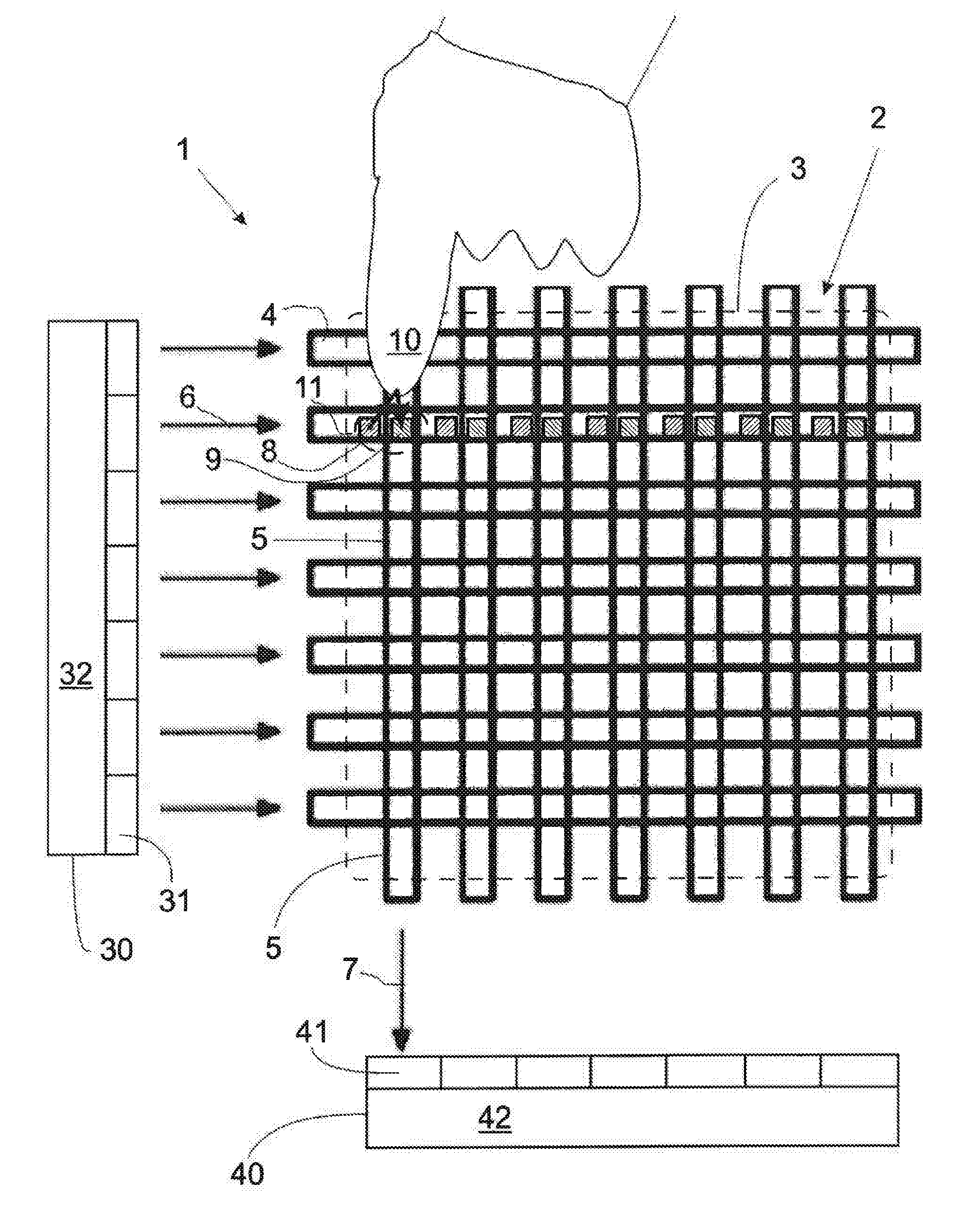
[0041]FIG. 1 illustrates a part of a touch sensing device comprising a light guide assembly 2 arranged in a touch sensitive area 3 of the touch sensing device.

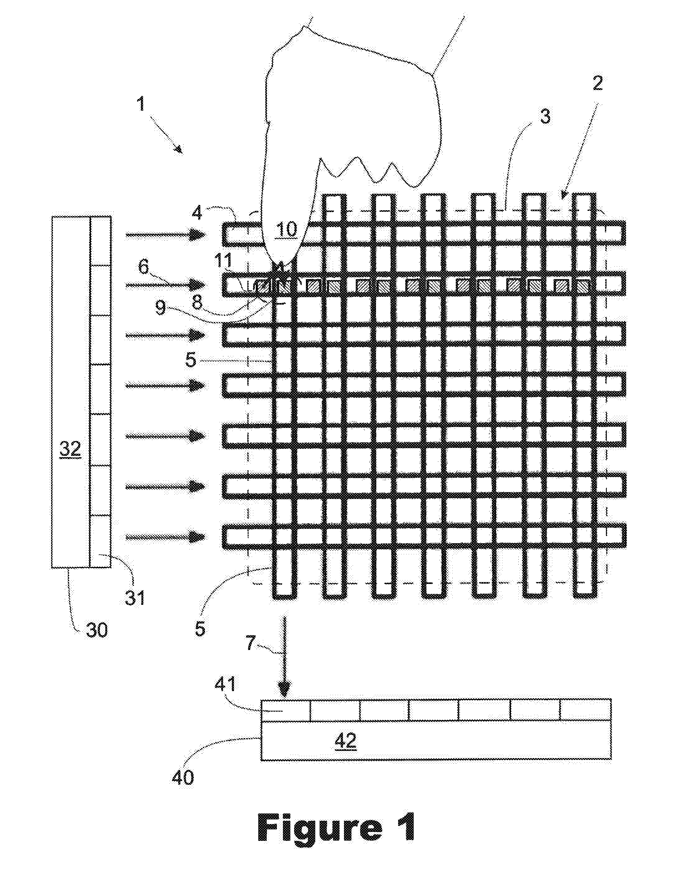
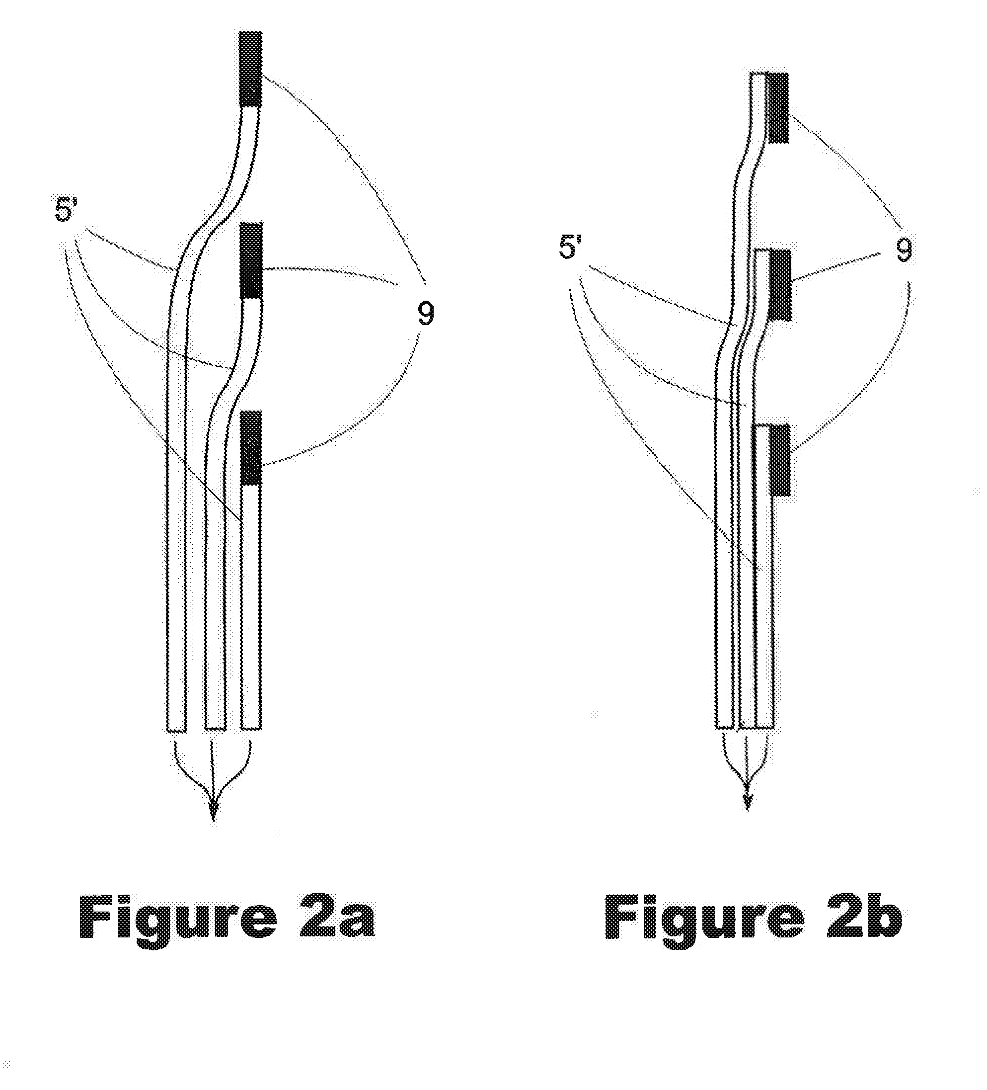
[0042]The light guide assembly 2 of FIG. 1 comprises two perpendicularly arranged arrays of light guide stripes 4, 5. The light guide stripes 4 of one of the arrays are designed for receiving illumination light 6, whereas the light guide stripes 5 of the other array are designed for delivering the light 7 propagated in the light guide assembly further out of the light guide assembly, as indicated by arrows marked in the drawing. Preferably, the illumination light lies in the infrared portion of the spectrum so that interference with the visible wavelengths emitted by the display of a touch screen or present in the ambient is minimized.

[0043]The light guide stripes 4, 5 of FIG. 1, as well as also the light guide stripes in the examples of the other Figures, can be designed and manufactured according to the principles and practi...


PUM


Abstract

A light guide assembly (2) for use in a touch sensitive area (3) of an optical touch sensing device (1) for touch screens is configured to receive light, to allow the light thereby received to propagate in the light guide assembly, and to deliver the light thereby propagated in the light guide assembly further out of the light guide assembly. The light guide assembly comprises a plurality of light guide stripes (4, 5) for controlling the propagation of light. The optical touch sensing device is configured to detect the presence of an external object (10) on the basis of changes in the light delivered further out of the light guide assembly due to interaction of the light with the external object. According to the invention, the light guide assembly comprises an interaction arrangement (8, 9) configured to define at least one restricted interaction area (11) within the touch sensitive area for interaction between the light and the external object, the interaction arrangement comprising a two-way coupling arrangement (8, 9; 12; 14; 15) configured to couple light out of the light guide assembly, out of one light guide stripe (4), and to couple a portion of the thereby out-coupled light, after reflection from the external object (10), back to the light guide assembly into a second light guide stripe (5).

Description

FIELD[0001]The present invention relates to touch sensing devices for touch screens, in particular to optical touch sensing devices, more particularly to optical touch sensing devices relying on interaction of light propagating in / via a light guide assembly with an external touching object.BACKGROUND[0002]User interfaces for different kinds of electrical apparatuses are nowadays more and more often realized by means of different types of touch screens, wherein a touch sensing device is superposed on or integrated in a display. In touch sensing devices, the user input is given by touching the touch sensitive area of the touch sensing device instead of operating conventional mechanical buttons, sliding bars, rollers, etc.[0003]Conventionally, such touch sensing devices have been configured to rely on purely electronic operation. Most commonly, touch sensing devices are based on resistive or capacitive touch sensitive films, wherein a touch by a finger or some other pointer changes the...

Claims


Application Information

Patent Timeline
IPC IPC(8): G06F3/042G02B6/35F21V8/00
CPCG06F3/0428G02B6/3522G02B6/005G06F2203/04109G06F3/0421
Inventor ILMONEN, TOMMIAYRAS, PEKKAHYVARINEN, HEIKKIVALIMAKI, MARCO
Owner MULTITOUCH
Why Eureka
Try Eureka