Sensor system processing architecture

a sensor system and processing architecture technology, applied in the field of noncontact imaging sensors, can solve the problems of system supplier supply of components, cost, etc., and achieve the effects of reducing the number of components, reducing the amount of cabling involved, and simple physical setup

Inactive Publication Date: 2016-06-16
LMI TECH
View PDF6 Cites 6 Cited by
  • Summary
  • Abstract
  • Description
  • Claims
  • Application Information

AI Technical Summary

Benefits of technology

[0006]It will be seen that one advantage of the present invention is to reduce the number of components that needs to be supplied by the system supplier. There is also a reduction in the cabling involved and a simpler physical set up.
[0007]The configuration of the prior art system of FIG. 1 usually involves a representative of the system supplier attending at the customer premises to verify the physical set up, initialize the software on the PC 10, oversee sensor calibration and configure the system software for a customer-appropriate user interface. The present invention allows a much simpler system installation and configuration as compared to the prior art. The attendance of a supplier representative at the customer premises, though sometimes desirable, is not necessary.
[0008]While the prior art approach centralizes system management in the PC, according to the invention, there is effectively no central system management thereby providing a simpler architecture and experience from the user's point of view.
[0009]These and other objects and advantages of the invention will be better understood by reference to the detailed description of the preferred embodiment that follows.SUMMARY OF THE INVENTION
[0010]According to the invention, each of a plurality of non-contact measurement optical sensors is equally enabled to perform identical functions so as to enable the joint imaging of an area or of an object in an area when the sensors are networked together. No separate management system is required, each sensor being enabled to provide system initialization, synchronization and management, image processing and metrological functions as well as client server functions.
[0011]Each sensor is substantially identical and is enabled to self detect its presence in a network of like sensors and to accept the assignment of, and to assume alternative respective roles for the sensors such that one of the sensors acts as a managing sensor, compiling and combining partial images or image information acquired by the other sensors in the network, providing synchronization and trigger signals to the other sensors and acting as the client server. This eliminates the need for a separate computer system to perform such functions. Each sensor is also able to alternatively accept the role of a support sensor so as not to enable those functions that are characteristic of a managing sensor. The managing sensor handles all imaging or image information compiling functions as well as client server functions.

Problems solved by technology

Although this configuration has long been the norm in the art, there is a cost in terms of the number of components being supplied by the system supplier.

Method used


Image

  • Sensor system processing architecture
  • Sensor system processing architecture
  • Sensor system processing architecture

Examples


Embodiment Construction

[0045]The following is a description of the preferred embodiment of the invention as presently contemplated. Not all possible embodiments within the scope of the invention are described.

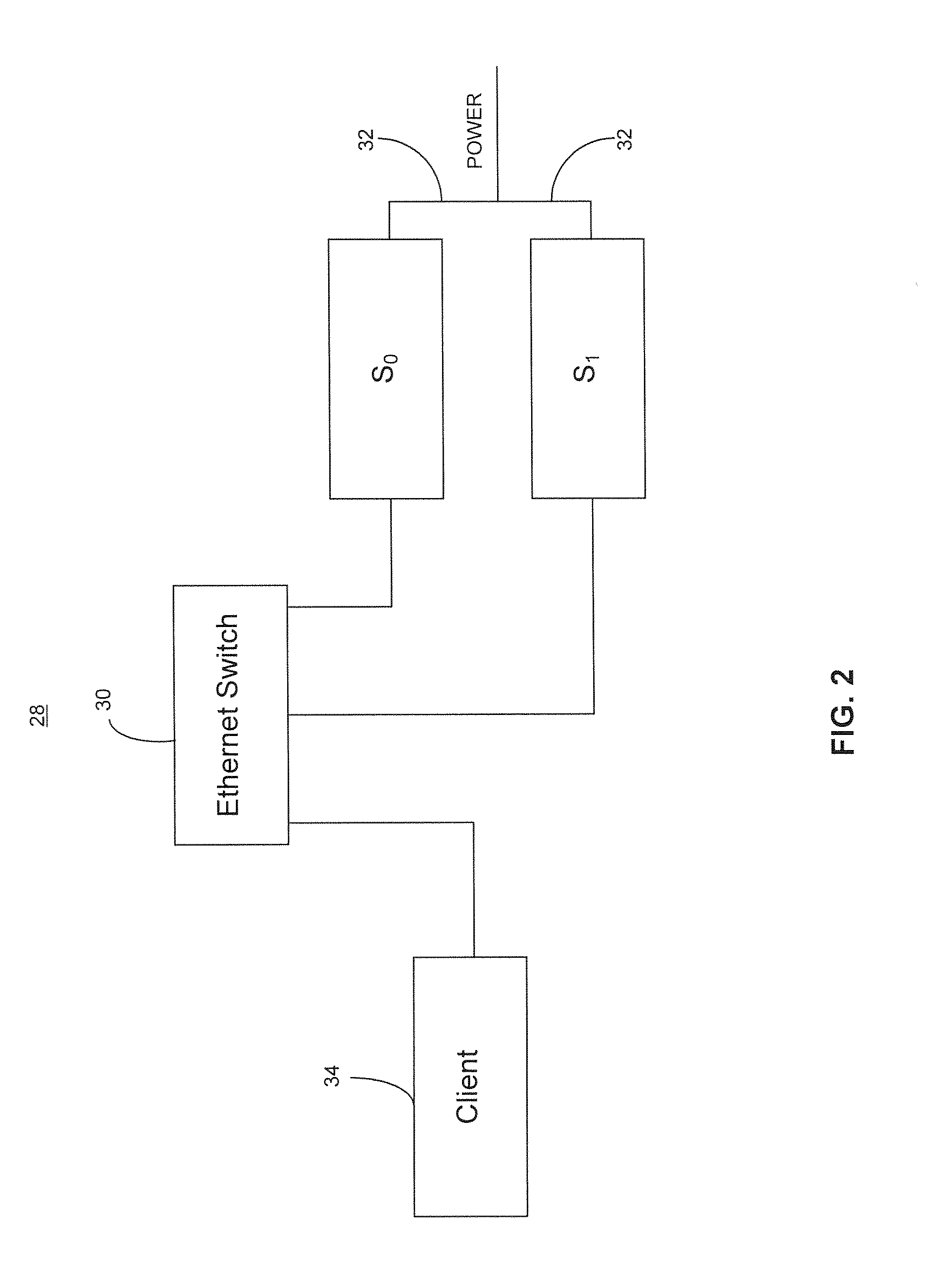
[0046]Referring now to FIG. 2, the preferred embodiment of the system 28 according to the invention comprises a managing sensor S0 and a support sensor S1. Although a single support sensor S1 is used in the preferred embodiment, additional support sensors S1 may be included in the system 28. The managing sensor S0 and the support sensor S1 are networked via network switch 30, preferably via Ethernet connections such that switch 30 is an Ethernet switch. Each sensor is preferably programmed with a factory assigned default IP address as well as a factory-assigned serial number.

[0047]Power is supplied to each sensor from a power source (not shown) by means of a cord set 32 connecting the sensors and that includes power cables. A client device 34, such as a computer with a user interface, may also be con...


PUM


Abstract

A system for imaging an area using a plurality of non-contact measurement optical sensors comprises a plurality of substantially identical sensors that detect the presence of a connected network of like sensors, accept the assignment of the role of a managing sensor or a support sensor and individually image a portion of said area. Each sensor may also individually derive image information from its image. The images or image information from each of the plurality of sensors are delivered to the managing sensor which combines them with its own image or image information and that acts as the exclusive client server for delivering the combined image or combined image information to the client.

Description

CROSS REFERENCE TO RELATED APPLICATIONS[0001]This application is a divisional application of U.S. patent application Ser. No. 13 / 089,151, filed Apr. 18, 2011, which application is incorporated herein in its entirety by this reference thereto.FIELD OF THE INVENTION[0002]This invention relates to non-contact imaging sensors. In particular the invention relates to non-contact imaging systems involving a plurality of sensors used to image the same object or area.BACKGROUND OF THE INVENTION[0003]Non-contact sensors are used to image or measure objects in a wide variety of applications including automated manufacturing processes, in the retail store environment and as embodied in various consumer products. A common type of non-contact sensor relies on the use of a camera to detect light reflected from an object in the field of view of the sensor. The geometrical relationship between the light source and the camera may be used to derive spatial and dimensional information about the object....

Claims


Application Information

Patent Timeline
Patent Type & Authority Applications(United States)
IPC IPC(8): G06T7/00G01B11/14G06T7/20G06T5/50H04N5/247H04N7/18
CPCG06T7/0085H04N5/247H04N7/181G06T7/2053G06T2207/20224G06T7/0018G01B11/14G06T2207/10016G06T5/50H04N7/18G06T7/80G06T7/13G06T7/254H04N23/90
Inventor ARDEN, TERRY
Owner LMI TECH
Why Eureka
Try Eureka