Medical image processing device and method for operating the same

a technology of medical image and processing device, applied in the field of medical image processing, to achieve the effect of eradicating the h

Active Publication Date: 2016-06-16
FUJIFILM CORP
View PDF10 Cites 6 Cited by
  • Summary
  • Abstract
  • Description
  • Claims
  • Application Information

AI Technical Summary

Benefits of technology

[0009]An object of the present invention is to provide a medical image processing device that produces an image in which uninfection of H. pylori, infection of the H. pylori, and successful eradication of the H. pylori are distinguished from each another and a method for operating a medical image processing device.

Problems solved by technology

In a case where diffuse redness appears in the image on the monitor, it is diagnosed that there is a high possibility of the presence of the H. pylori, which is likely to cause cancer.

Method used


Image

  • Medical image processing device and method for operating the same
  • Medical image processing device and method for operating the same
  • Medical image processing device and method for operating the same

Examples


embodiment 1a

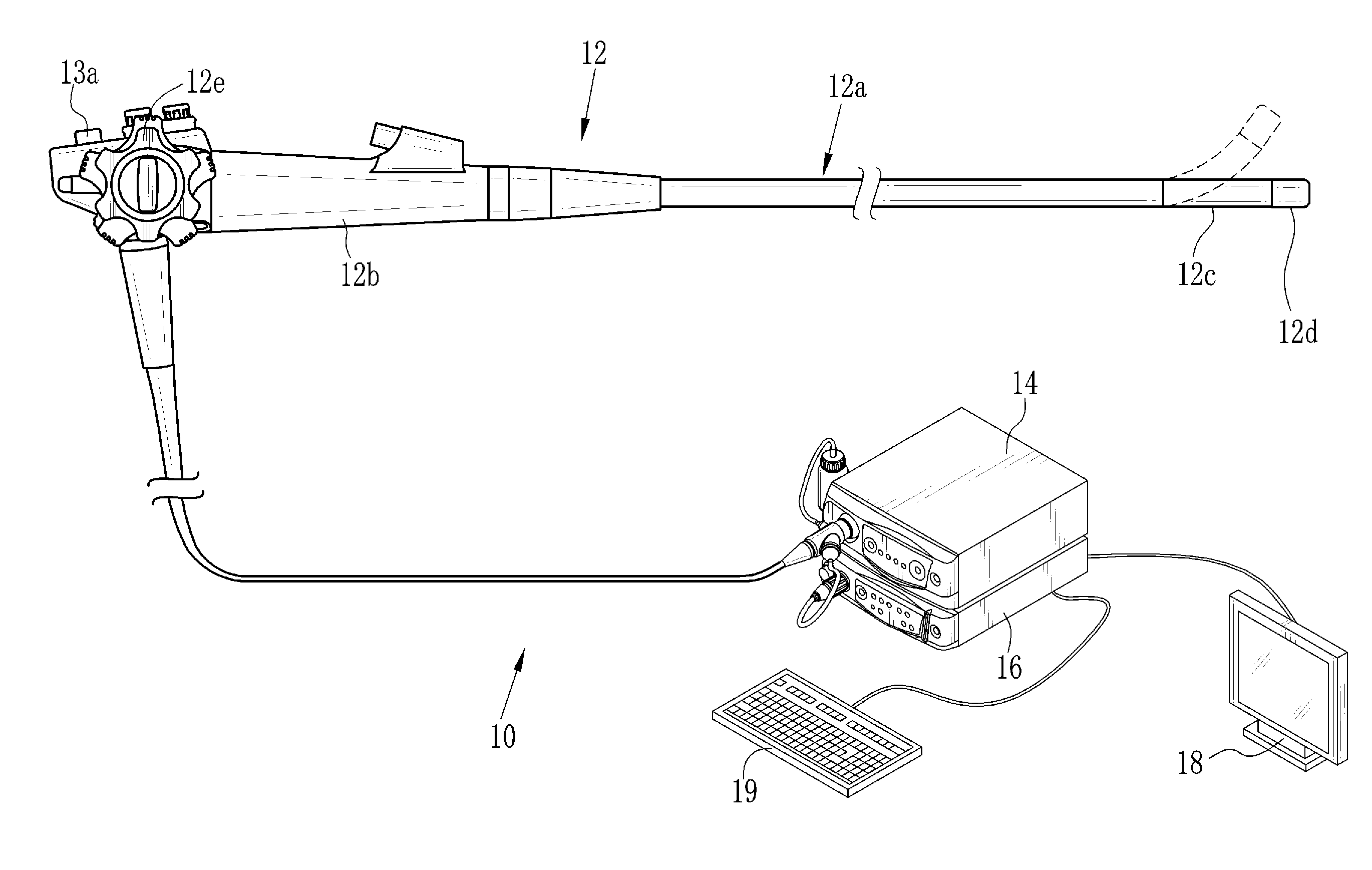
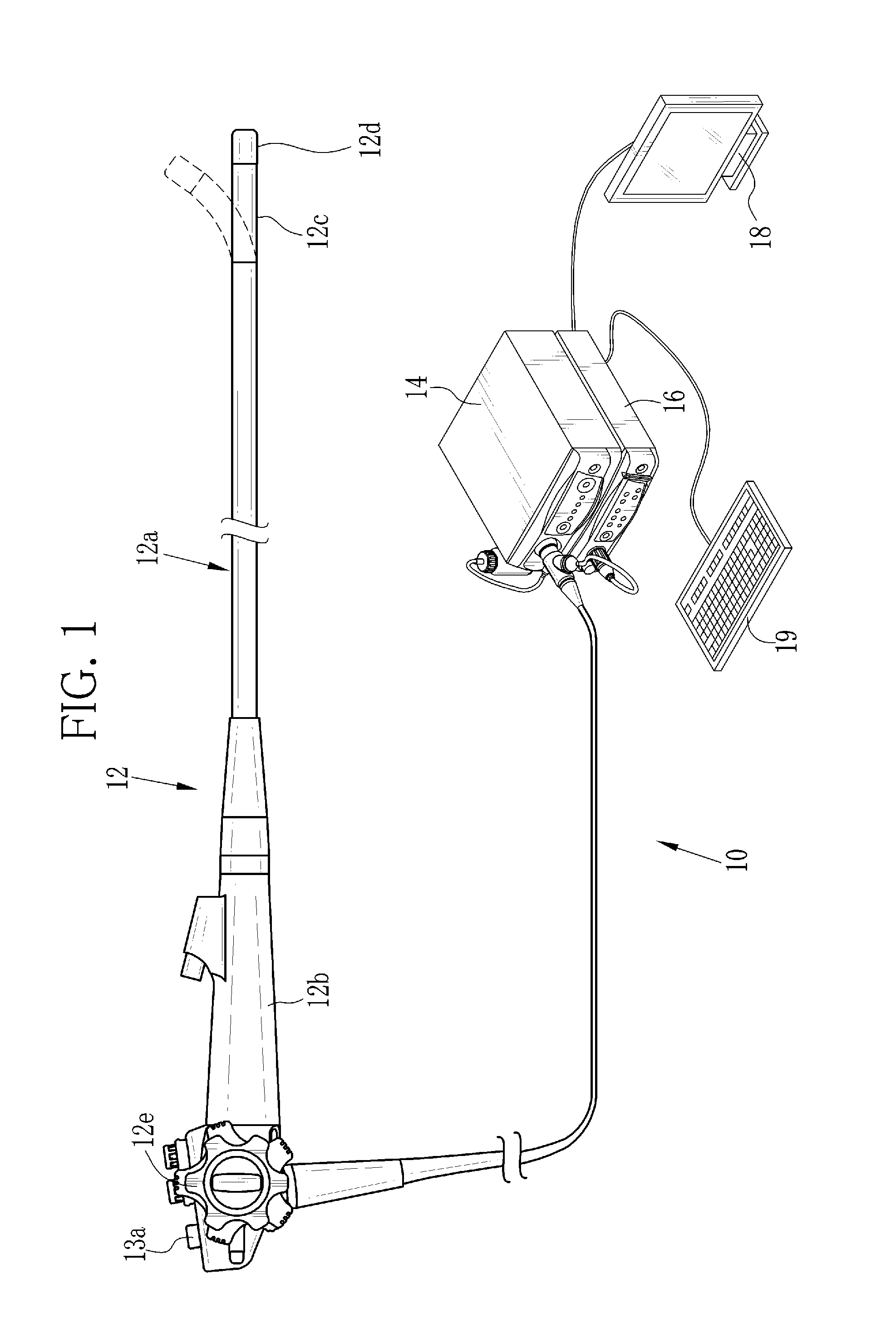
[0057]In FIG. 1, an endoscope system 10 according to an embodiment 1A comprises an endoscope 12, a light source device 14, a processor device 16, a monitor 18, and a console 19. The endoscope 12 is connected optically to the light source device 14 and electrically to the processor device 16. The endoscope 12 comprises an insertion section 12a to be inserted into a body cavity, a control handle unit 12b provided at the proximal end of the insertion section 12a, a flexible portion 12c, which is provided on the distal side of the insertion section 12a, and a distal end portion 12d coupled to the flexible portion 12c. The flexible portion 12c is bent by operating an angle knob 12e of the control handle unit 12b. Thereby the distal end portion 12d is directed to a desired direction.

[0058]The control handle unit 12b is provided with the angle knob 12e and a mode switch (SW) 13a. The mode SW 13a is operated to switch between a normal mode and a special mode. In the normal mode, a normal im...

embodiment 1b

[0101]In the above embodiment 1A, the signal ratio calculator 72 calculates the B / G ratio and the G / R ratio from the first RGB image signals. In the feature space formed by the B / G ratio and the G / R ratio, “the equal angular magnification process and the angle expansion process or the angle compression process” and “the equal radial-coordinate magnification process and the radial-coordinate expansion process or the radial-coordinate compression process” are performed. In an embodiment 1B, chrominance signals Cr and Cb are obtained as the color information. In a feature space formed by the chrominance signals Cr and Cb, “the equal angular magnification process and the angle expansion process or the angle compression process” and “the equal radial-coordinate magnification process and the radial-coordinate expansion process or the radial-coordinate compression process” are performed.

[0102]In the embodiment 1B, a special image processor 92 (see FIG. 15) is used. Unlike the special image...

embodiment 1c

[0107]In an embodiment 1C, a lab converter (which corresponds to the color information obtaining section of the present invention, for example) performs lab conversion of the first RGB image signals to obtain a* and b* (that is, the color components a* and b* (the color information in this embodiment) of CIE lab space, and the same applies to the following). In a feature space (ab space) formed by a* and b*, “the equal angular magnification process and the angle expansion process or the angle compression process” and “the equal radial-coordinate magnification process and the radial-coordinate expansion process or the radial-coordinate compression process” are performed. Note that CIE Lab refers to a color system defined by CIE (Commission internationale de l'éclairage or International Commission on Illumination).

[0108]In this embodiment, a special image processor 82 (see FIG. 19) is used. Unlike the special image processor 64, the special image processor 82 is not provided with the ...


PUM


Abstract

RGB image signals are inputted. A B / G ratio is calculated from the B and G image signals. A G / R ratio is calculated from the G and R image signals. First, second, and third areas are located in a feature space formed by the B / G and G / R ratios. An equal angular magnification process is performed on an angle in a region R1x including a first reference line passing through the second area. An angle expansion process or an angle compression process is performed on an angle in a region R1y located outside the region R1x. An equal radial-coordinate magnification process is performed on a radial coordinate in a region R2x, which includes a second reference line passing through the second area and intersecting the first reference line. A radial-coordinate expansion process or a radial-coordinate compression process is performed on a radial coordinate in a region R2y located outside the region R2x.

Description

CROSS-REFERENCE TO RELATED APPLICATIONS[0001]The present application claims priority under 35 U.S.C. §119 to Japanese Patent Application No. 2014-250227, filed Dec. 10, 2014. Each of the above application(s) is hereby expressly incorporated by reference, in its entirety, into the present application.BACKGROUND OF THE INVENTION[0002]1. Field of the Invention[0003]The present invention relates to a medical image processing device that enables displaying a medical image that is a captured image of an object of interest in a body cavity and a method for operating a medical image processing device.[0004]2. Description Related to the Prior Art[0005]In diagnosing stomach cancer, it has been recognized that the onset of the stomach cancer is closely related to the presence of Helicobacter pylori (H. pylori). In 1994, WHO (the World Health Organization) announced that the H. pylori is a carcinogen. The eradiation of the H. Pylori infection has been performed to reduce the stomach cancer. Aft...

Claims


Application Information

Patent Timeline
Patent Type & Authority Applications(United States)
IPC IPC(8): G06T7/60G06K9/52G06K9/46G06T7/00G06T7/40
CPCG06T7/60G06T7/0014G06T7/408G06T2207/30092G06K9/52G06K9/4661G06K2009/4666G06K9/4652G06T7/90A61B5/004A61B5/0084A61B5/4238A61B5/6852A61B5/6886G06T7/0012
Inventor KURAMOTO, MASAYUKISUGIZAKI, MAKOTO
Owner FUJIFILM CORP
Why Eureka
Try Eureka