
Temperature control system for semiconductor manufacturing system

a temperature control system and manufacturing system technology, applied in the direction of lighting and heating apparatus, machines using electric/magnetic effects, refrigerating machines, etc., can solve the problems of reducing the efficiency of power, and reducing the power consumption of adjusting the temperature of the recovered heating medium to the set temperatures of the cooling means, so as to minimize the generation of undershoot or overshoot, the effect of optimizing the power consumption of cooling or heating

Active Publication Date: 2016-06-16
TECHEST
View PDF7 Cites 7 Cited by
  • Summary
  • Abstract
  • Description
  • Claims
  • Application Information

AI Technical Summary

Benefits of technology

This patent describes a temperature control system for a semiconductor manufacturing system that can quickly control the temperature of the heating medium supplied to the load, while minimizing power consumption. It achieves this by mixing a cooled heating medium and a heated heating medium at precise ratios, and then distributing the recovered heating medium back into the thermoelectric element and heater in the same proportions. This system also addresses the issue of abrupt variations in temperature by maintaining the temperature of the recovered heating medium and the bypassed heating medium at a set level, and by cooling or heating the heating medium to a target temperature upon recovery and supply to the heating medium tank. Overall, this system improves the efficiency and accuracy of temperature control in semiconductor manufacturing equipment.

Problems solved by technology

In particular, in recent times, while variation in temperature is required even in a unit step of the process recipe, it is difficult for an external temperature control system to deal with the variation in temperature.
Eventually, since such a configuration cannot easily use the external temperature control, which requires a relatively long time to deal with the variation in temperature, and enforces an abrupt variation in temperature through the tunable heater, efficiency in power is substantially degraded.
Since an unstable state upon temperature control continues for a substantially long time due to a substantial thermal capacity of the electrostatic chuck, the heating medium having a sufficient flow rate is required for the temperature control.
However, in most cases, since the heating medium recovered from the electrostatic chuck is equally supplied to heating medium tanks (reservoirs) of a cooling means and a heating means, power consumption for adjusting the temperature of the recovered heating medium to the set temperatures of the cooling means and the heating means becomes severe.
In addition, since a substantial thermal shock is generated when a difference between the temperature of the recovered heating medium and a temperature to be controlled is abruptly increased due to a variation in temperature required by a load, overshoot or undershoot is frequently generated when dealing with the temperature using a conventional control method (for example, proportional-integral-derivative (PID) control), which makes it difficult to control the temperature.

Method used


Image

  • Temperature control system for semiconductor manufacturing system
  • Temperature control system for semiconductor manufacturing system
  • Temperature control system for semiconductor manufacturing system

Examples


Embodiment Construction

[0039]Exemplary embodiments of the present invention will be described in detail below with reference to the accompanying drawings. While the present invention is shown and described in connection with exemplary embodiments thereof, it will be apparent to those skilled in the art that various modifications can be made without departing from the spirit and scope of the invention.

[0040]Embodiments of the present invention will be described with reference to the accompanying drawings.

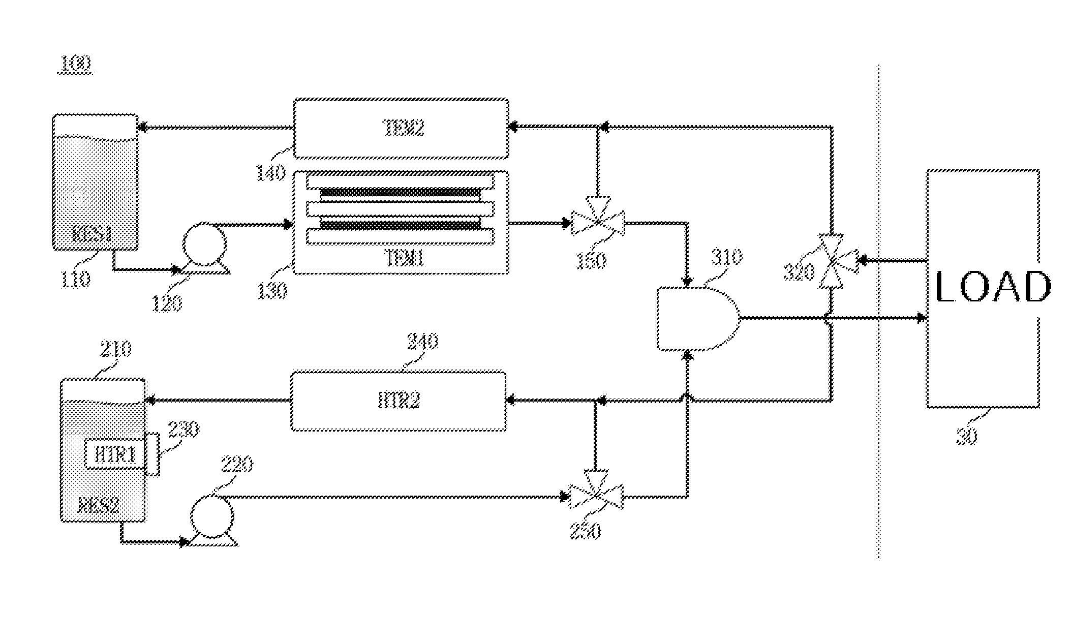
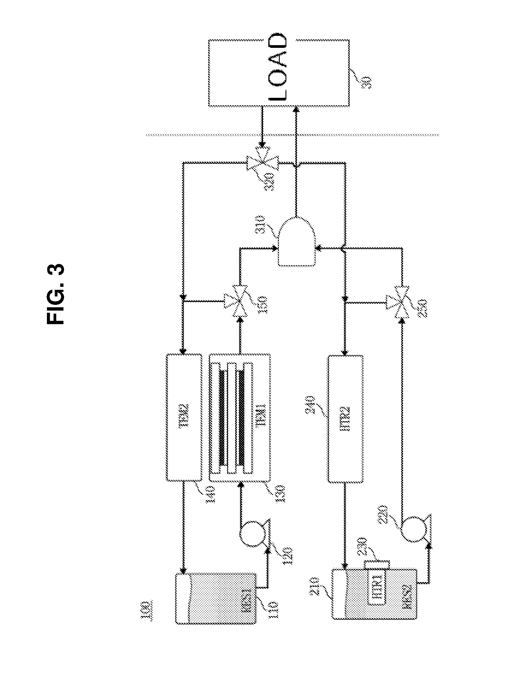
[0041]First, FIG. 3 shows a configuration of a temperature control system 100 for a semiconductor manufacturing system according to an embodiment of the present invention. As shown, a chiller unit 110 to 150 is provided at an upper end, a heater unit 210 to 250 is provided at a lower end, and a mixer 310 and a 3-way switching valve are provided at a right side connected to a load 30.

[0042]The temperature control system 100 is a temperature control system configured to mix a heating medium cooled through th...


PUM


Abstract

Provided is a temperature control system configured to mix a low temperature heating medium and a high temperature heating medium to supply the heating mediums at a temperature according to a process recipe to an electrostatic chuck (ESC) configured to maintain a temperature and support a wafer in a chamber in which a semiconductor wafer processing process is performed, and a heating medium obtained by mixing a heating medium cooled through a thermoelectric element and a heating medium heated through a heater to a desired target temperature according to a first ratio and a second ratio is provided to a load and recovered from the load, and the heating medium is distributed to the thermoelectric element and the heater according to the first ratio and the second ratio, which are ratios upon the mixing, optimizing power consumption for cooling or heating.

Description

CROSS-REFERENCE TO RELATED APPLICATION[0001]This is a division of application Ser. No. 14 / 263,498, filed Apr. 28, 2014. Further, this application claims priority to and the benefit of Korean Patent Application No. 2013-0124093, filed on Oct. 17, 2013, the disclosure of which is incorporated herein by reference in its entirety.BACKGROUND[0002]1. Field of the Invention[0003]The present invention relates to a temperature control system for a semiconductor manufacturing system, and more particularly, to a temperature control system configured to mix a low temperature heating medium and a high temperature heating medium to supply the heating medium to an electrostatic chuck (ESC) configured to maintain a temperature while supporting a wafer in a chamber in which a semiconductor wafer processing process is performed at a temperature according to a process recipe.[0004]2. Discussion of Related Art[0005]As semiconductor device technology gradually advances, control precision of equipment ap...

Claims


Application Information

Patent Timeline
Patent Type & Authority Applications(United States)
IPC IPC(8): H01L21/67F25B21/02
CPCF25B21/02H01L21/67109H01L21/67248H01L21/6831H01L21/02F25B2321/021F28F27/02
Inventor HAN, MIN JINKIM, JAE GEON
Owner TECHEST
Learn More