
Blenderblade assembly and shaft assembly thereof

a technology of blade blades and shafts, applied in the direction of shafts, strainers, kitchen equipment, etc., can solve the problems of shaft body directly touching the oil seal, prone to wear, and affecting the work efficiency of people, so as to ensure watertightness

Inactive Publication Date: 2016-06-23
LEE MING HSIEN
View PDF24 Cites 5 Cited by
  • Summary
  • Abstract
  • Description
  • Claims
  • Application Information

AI Technical Summary

Benefits of technology

The present invention improves the shaft assembly of a blender blade device by preventing the shaft body from rubbing against other objects, which may cause gaps and compromise its watertightness. The wear-resistant sleeve around the shaft body fits tightly with an oil seal and reduces friction damage and the chance of forming a gap, ensuring the shaft assembly remains watertight even after long use. Additionally, waterproof rings are placed between the shaft body and the oil seal to further reduce the chance of forming a gap and improve the effectiveness of waterproofing.

Problems solved by technology

The modern life makes people suffer from working pressure and lack of exercise.
In the existing configuration, the shaft body directly contacts the oil seal and tends to get worn after long-term use.
However, when the shaft body is worn after long-term use, gaps can generate between the shaft body and the watertight pad, making the watertight pad gradually lose its filling and water-blocking functions.
This may damage the bearing and even the motor in the base.

Method used


Image

  • Blenderblade assembly and shaft assembly thereof
  • Blenderblade assembly and shaft assembly thereof
  • Blenderblade assembly and shaft assembly thereof

Examples


Embodiment Construction

[0014]The present invention is hereunder described in terms of structures and features, illustrated with embodiments, and depicted by the accompanying drawings.

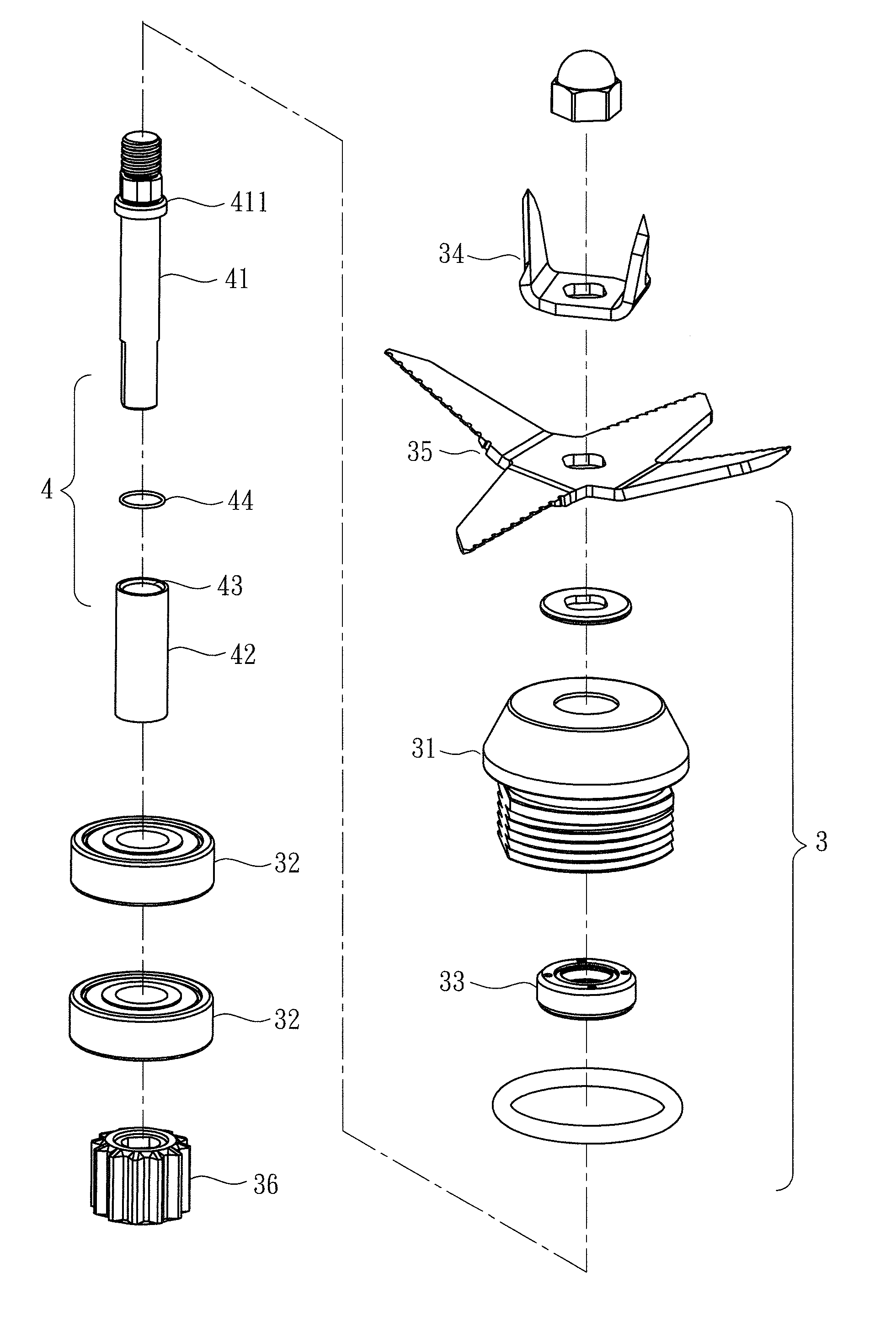
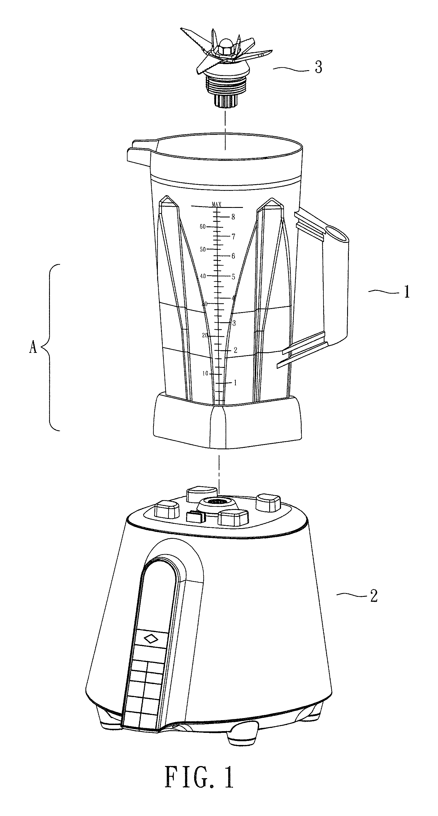
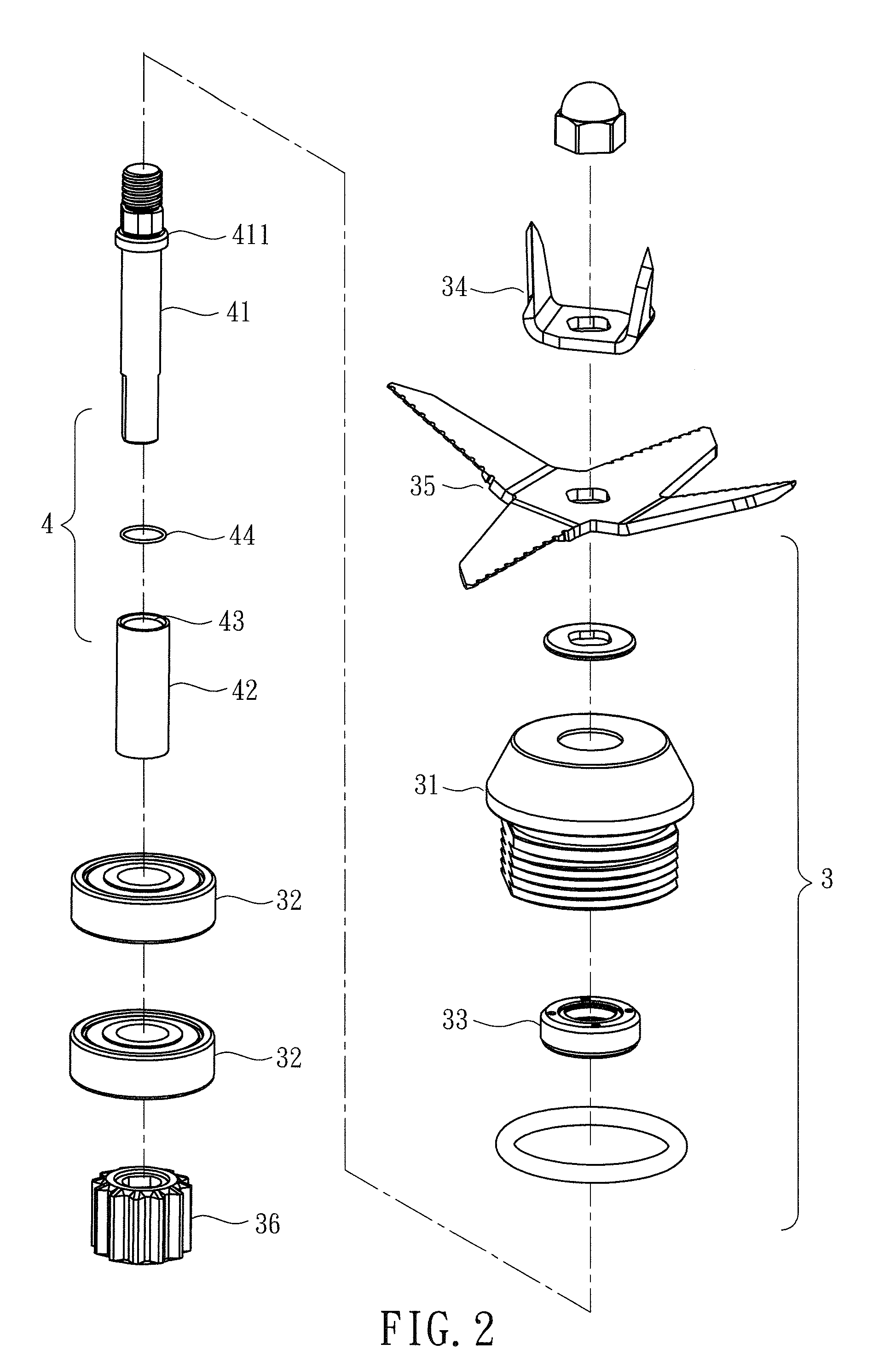
[0015]Referring to FIG. 1 and FIG. 4, a blender A essentially comprises a blender base 2, a blender container 1 and a blender blade device 3. The blender base 2 has its power supplied by a motor. The blender container 1 is operably disposed at the top of the blender base 2. The blender blade device 3 is operably connected to a transmission portion of the motor. The blender blade device 3 is disposed in the blender container 1 and penetratingly disposed at the bottom of the blender container 1. The present invention relates to a shaft assembly of a blender blade device 3. The blender blade device 3 comprises a shell 31 which opens downward. A bearing 32 with an axially-penetrating hole and an oil seal 33 with an axially-penetrating hole are sequentially stacked in a bottom-to-top manner inside the shell 31. A penetrating hole ...


PUM


Abstract

A shaft assembly (4) of a blender blade device (3) is provided. The blender blade device (3) is penetrated by the shaft assembly (4) and disposed in a blender container (1) and penetratingly disposed at the bottom of the blender container (1) to operably connect with a blender base (2). The shaft assembly (4) comprises a shaft body (41) and a wear-resistant sleeve (42). A stop ring (411) is disposed at the upper segment of the shaft body (41) and axially protrudes outward from the circumferential wall of the shaft body (41). The wear-resistant sleeve (42) axially fits around the outer wall of the shaft body (41) and has the top rim abutting against the bottom rim of the stop ring (411). The outer circumferential wall of the shaft body (41) is protected against direct contact and friction. With the wear-resistant sleeve (42) being wear-resistant and the shaft body (41) being immune to friction-induced damage, the shaft body (41) is unlikely to get spaced apart from watertight rings (44) even after long use, thereby waterproofing the shaft assembly (4).

Description

BACKGROUND OF THE INVENTION[0001]1. Technical Field[0002]The present invention relates to watertightness of knife shafts, and more particularly to a watertight structure applicable to a shaft assembly of a blender blade device.[0003]2. Description of Related Art[0004]The modern life makes people suffer from working pressure and lack of exercise. For maintaining a healthy condition, people tend to increase daily ingestion of cellulose and vitamins by taking fruit juice that is made through cutting and blending fresh vegetables and fruits with a blender, with the hope that quick absorption of natural nutrition helps to preserve our health.[0005]A blender typically has a base powered by a motor, a container mounted on and operated by the base, and a blade device that is driven by the motor. The blade device is installed in the container and passes through the bottom of the container. Such a blade device usually has a downward-opened shell. The shell receives therein a bearing having an...

Claims


Application Information

Patent Timeline
Patent Type & Authority Applications(United States)
IPC IPC(8): A47J43/08F16C3/02
CPCF16C3/023A47J43/085A47J43/0716A47J19/02F16C2314/00A47J43/0722A47J19/06
Inventor LEE, MING-HSIEN
Owner LEE MING HSIEN
Learn More