
Cleaning apparatus

a technology of cleaning apparatus and cleaning hose, which is applied in the direction of suction cleaners, suction hoses, domestic applications, etc., can solve the problems of blocked flow paths, and achieve the effect of improving structure and increasing dust collection efficiency

Active Publication Date: 2016-06-23
SAMSUNG ELECTRONICS CO LTD
View PDF12 Cites 51 Cited by
  • Summary
  • Abstract
  • Description
  • Claims
  • Application Information

AI Technical Summary

Benefits of technology

The invention is about a cleaner that has a more efficient motor to collect dust. It has a communication hole that allows foreign matter to move towards the dust collector, and a rib that prevents dust from flowing back into the cyclone unit. These features make it easier to remove dust and keep it clean.

Problems solved by technology

However, since foreign matter primarily filtered by the dust collector is larger than foreign matter filtered by the cleaning apparatus body, a flow path may be blocked and noise may be made thereby.

Method used


Image

  • Cleaning apparatus
  • Cleaning apparatus
  • Cleaning apparatus

Examples


Embodiment Construction

[0065]Reference will now be made in detail to embodiments of the disclosure, examples of which are illustrated in the accompanying drawings, wherein like reference numerals refer to like elements throughout.

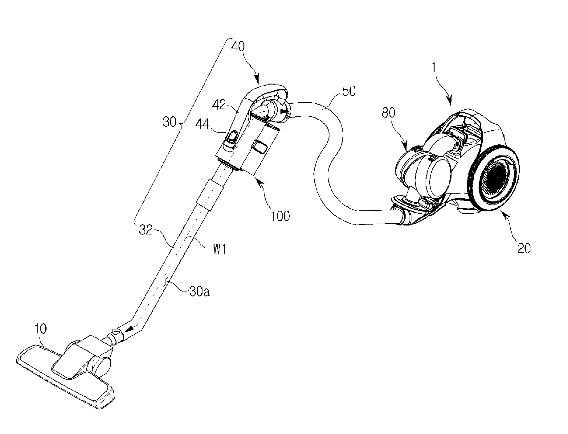
[0066]FIG. 1 is a perspective view illustrating a cleaning apparatus according to an embodiment of the disclosure.

[0067]A vacuum cleaning apparatus according to an exemplary embodiment may include a cleaning apparatus body 1, a body dust collector (not shown), a head unit 10, and a wheel assembly 20. The body dust collector (not shown) and the wheel assembly 20 are mounted on the cleaning apparatus body 1. A suction part provided at the head unit 10 may contact a surface to be cleaned and sucks foreign matter from the surface. The vacuum cleaning apparatus according to an embodiment may be a canister type vacuum cleaning apparatus.

[0068]The cleaning apparatus body 1 may include a drive unit (not shown) to generate suction force. The cleaning apparatus body 1 may move on a floor b...


PUM


Abstract

A cleaning apparatus includes a dust collector detachably installed at a cleaning stick. The dust collector includes a cyclone unit to generate a cyclone stream and a dust collecting unit to collect foreign matter. In this structure, a dust collecting efficiency of the dust collector may be increased, and a load of a cleaning apparatus body may be reduced.

Description

CROSS-REFERENCE TO RELATED APPLICATIONS[0001]This application claims the priority benefit of Korean Patent Application No. 10-2014-0183355, filed on Dec. 18, 2014 in the Korean Intellectual Property Office, the disclosure of which is incorporated herein by reference.BACKGROUND[0002]1. Field[0003]Embodiments of the disclosure relate to cleaning apparatuses, and more particularly, to cleaning apparatuses including a dust collector having an improved structure.[0004]2. Description of the Related Art[0005]In general, cleaning apparatuses have been developed for the convenience of cleaning. Vacuum cleaning apparatuses to collect foreign matter from a floor by using suction force generated by a motor and mopping cleaning apparatuses to mop the floor have been widely used.[0006]A vacuum cleaning apparatus generally may include a head unit closely contacting a surface to be cleaned and a main body generating suction force which sucks foreign matter placed on the surface to be cleaned using ...

Claims


Application Information

Patent Timeline
Patent Type & Authority Applications(United States)
IPC IPC(8): A47L5/36A47L9/16A47L9/24A47L9/19
CPCA47L5/362A47L9/19A47L9/244A47L9/1683A47L9/1691A47L9/1608A47L5/24A47L9/16A47L9/1616A47L9/165
Inventor HAN, JUNG GYUNKIM, SHINLIM, WON KYU
Owner SAMSUNG ELECTRONICS CO LTD
Learn More