Laundry treating appliance
- Summary
- Abstract
- Description
- Claims
- Application Information
AI Technical Summary
Benefits of technology
Problems solved by technology
Method used
Image
Examples
first embodiment
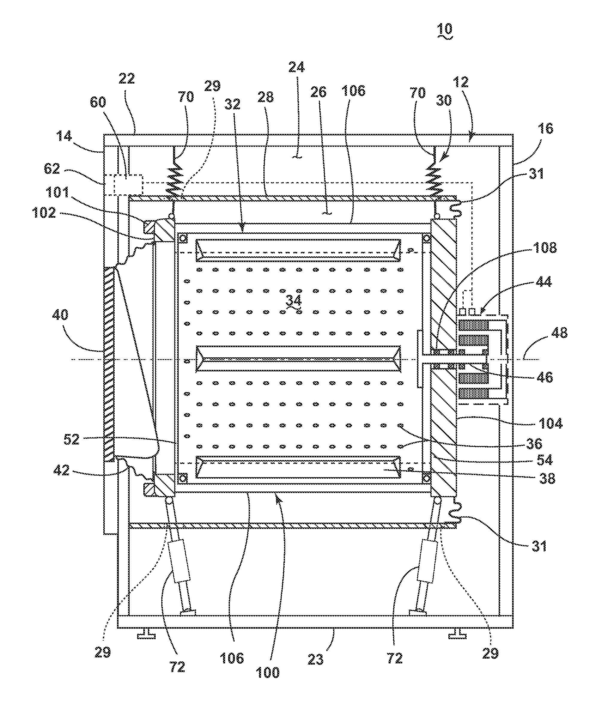
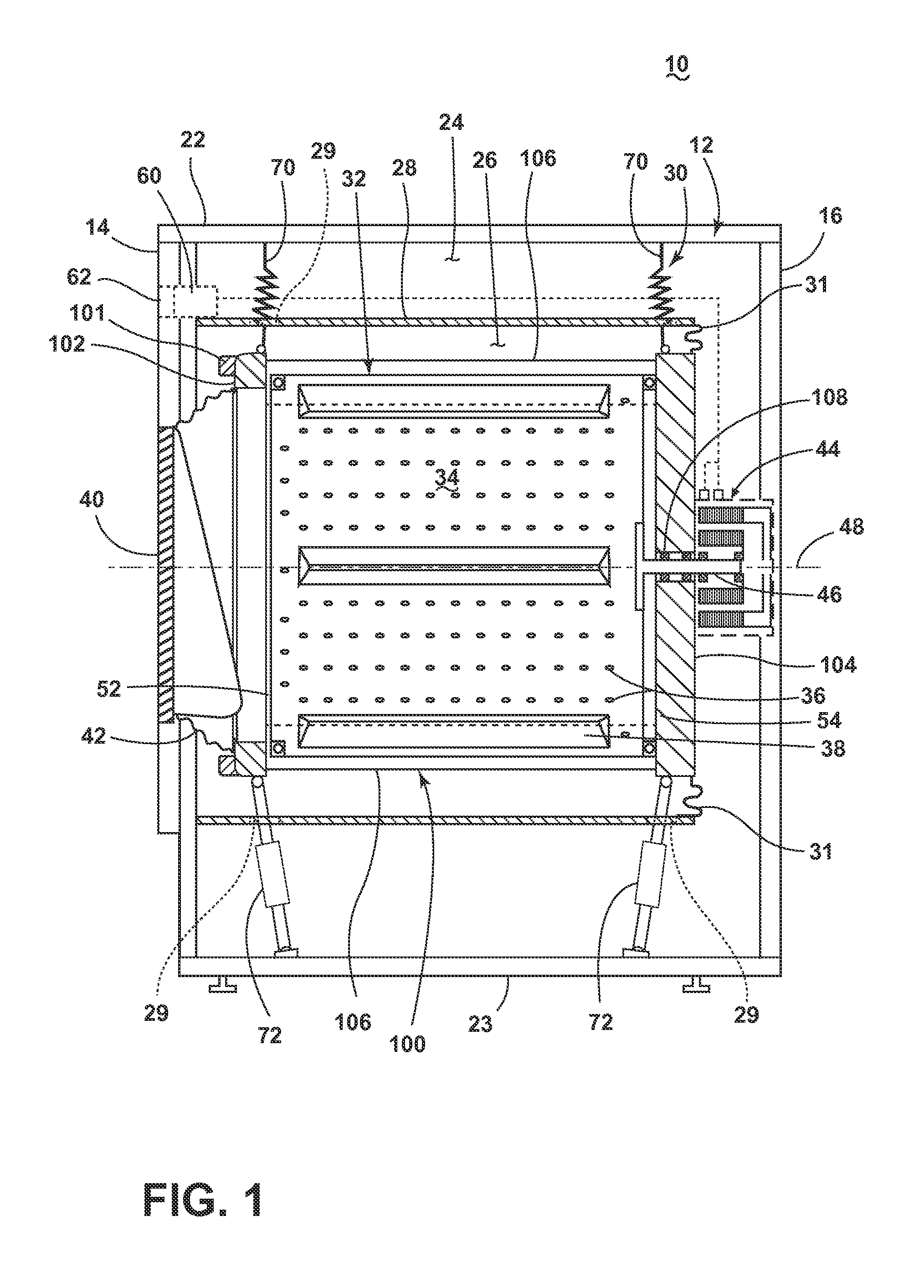
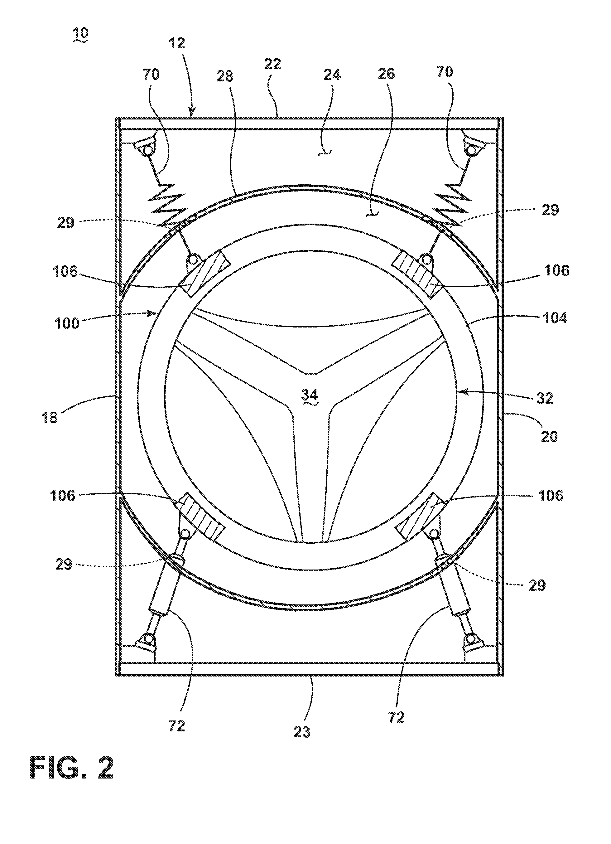
[0038]Turning now to FIG. 6, the suspension seals 118 is shown in the form of a bellows 120. The damper 72 is shown comprising a damper body 122 and a damper rod 124, coupling to the exoskeleton 100 at a suspension mount 126. The damper rod 124 can actuate, sliding in and out of the damper body 122 and permitting the dynamic movement of the exoskeleton 100 relative to the tub 28.
[0039]The bellows 120 has a somewhat sinusoidal profile common to bellows 120, while any profile shape, such as an “S” shaped bellows 120, is contemplated. The bellows 120 further comprises a bellows top 128, coupled to the suspension mount 126, and a bellows bottom 130, coupled to a wall 142 defining the suspension opening 29. The bellows 120 can mount to suspension mount 126 and the wall 142 by any method known in the industry, such as welding, adhesives, or fasteners. The bellows 120 is generally annular and surrounds the damper 72 to define a bellows space 134 between the bellows 120 and the damper 72, w...
second embodiment
[0044]Turning now to FIG. 9, a variation on the second embodiment cap 144 is shown. An extended cap 152 differs from the cap 144 of FIG. 8, in that it has a rounded top 153 as compared to the flat top of the cap 144 in FIG. 8. The rounded top 153 extends upwardly to surround a portion of the damper rod 124. As with the cap 144 of FIG. 8, the extended cap 152 comprises additional slits 150. The extended cap 152 disposed around the damper rod 124 provides a liquid-tight seal at the damper rod 124 rather than at the damper body 122. The additional slits 150 support the actuation of the damper rod 124 against the cap 144, while maintaining the liquid-tight seal by providing a space in which the cap 144 can expand or compress with the movements of the damper rod 124.
[0045]Turning now to FIG. 10, a third embodiment of the suspension seal 118 is also a combination of the wall and cap, like the second embodiment, with the cap being an umbrella 156 that overlies the wall 142 to collectively ...
third embodiment
[0049]Turning now to FIG. 11 a variation on FIG. 10 is shown. The umbrella 156 now mounts to the damper rod 124 at the umbrella passage 154, such that the umbrella 156 can move in concert with the damper rod 124 during actuation. The umbrella peripheral wall 160 is elongated to remain disposed around the wall 142 at the umbrella gap 162, defining the labyrinth seal between the wall 142 and the umbrella peripheral wall 160. During the downward actuation of the damper rod 124, the umbrella 156 will move downward, preventing the liquid 164 from splashing over the wall 142 caused by the movement of the exoskeleton 100.
[0050]While the embodiments disclosed herein describe three different embodiment of seals utilized within a horizontal-axis, laundry treating appliance with a fixed tub, additional seals are contemplated. Non-limiting examples of seals can include adhesives, rings, heat seals, couplings, hermetic seals, gaskets, plugs, etc.
[0051]Additionally, while the embodiment described...
PUM
 Abstract
Description
Claims
Application Information
 - R&D
- Intellectual Property
- Life Sciences
- Materials
- Tech Scout
- Unparalleled Data Quality
- Higher Quality Content
- 60% Fewer Hallucinations
Browse by: Latest US Patents, China's latest patents, Technical Efficacy Thesaurus, Application Domain, Technology Topic, Popular Technical Reports.
© 2025 PatSnap. All rights reserved.Legal|Privacy policy|Modern Slavery Act Transparency Statement|Sitemap|About US| Contact US: help@patsnap.com


